Heating unit baseplate
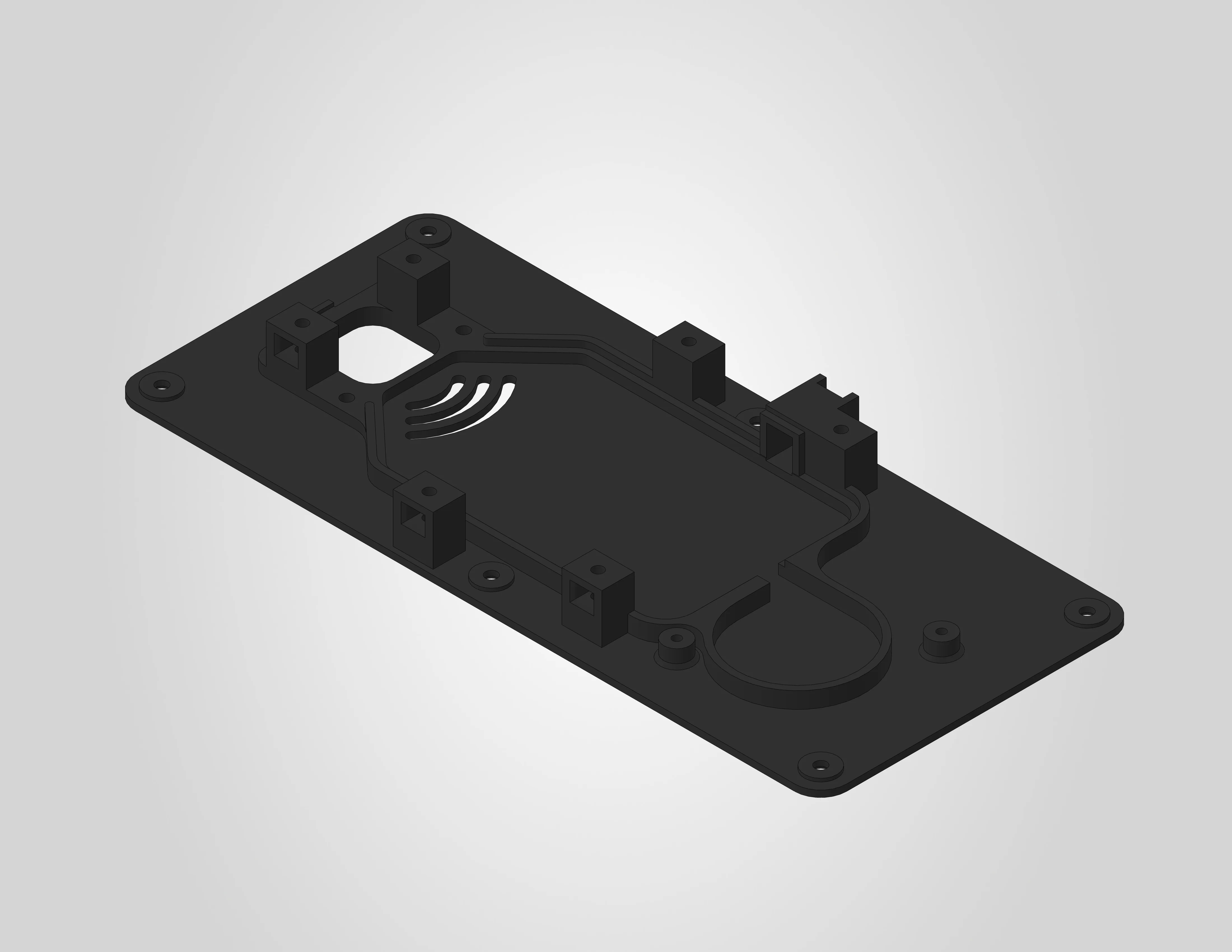
The heating unit baseplate is the main structural part of the heating unit assembly. The 3MF file is pre-configured for a Bambu Lab H2S printer with the settings below already applied. If you are using a different printer, use the settings below as a reference.
A STEP file is also included for users who wish to slice the model independently or adapt it for a different printer.
| Dimensions | 218.8 x 98.1 x 17.2 mm |
| Estimated print time | ~1 hour 41 minutes |
| Recommended material | ABS |
Before you print
Clean your build plate
Clean your build plate before printing to prevent warping. Wash the engineering plate with lukewarm water and dish soap, then dry it thoroughly before placing it on the printer.
ABS requires proper ventilation
ABS produces fumes during printing. Make sure your printer is enclosed and the room is well ventilated.
Pre-drying is required
ABS is sensitive to moisture and must be dried before printing. Follow the filament manufacturer's drying instructions.
Filament settings
The .3mf file uses the generic Bambu Lab ABS profile. No parameters were changed from the default profile.
It is recommended to use ABS, as this part has been tested and validated with Bambu Lab ABS. Other ABS brands should work as well.
Other materials
Other materials may work, but must have at least the same heat resistance as ABS, as these parts are exposed to elevated temperatures during operation. Alternative materials have not been officially tested or validated. Using them is at your own risk and may affect dimensional accuracy and fit.
Workspace settings
The following workspace settings were changed from the default settings:
| Setting | Value |
|---|---|
| Nozzle | 0.4 mm |
| Layer height | 0.2 mm |
| Build plate | Engineering plate |
| Sparse infill pattern | Gyroid |
| Supports | enabled |
| Type of support | tree (auto) |
| Support style | Default |
No adhesives needed
No glue or other adhesives are required on the engineering plate for this print.
Support blockers
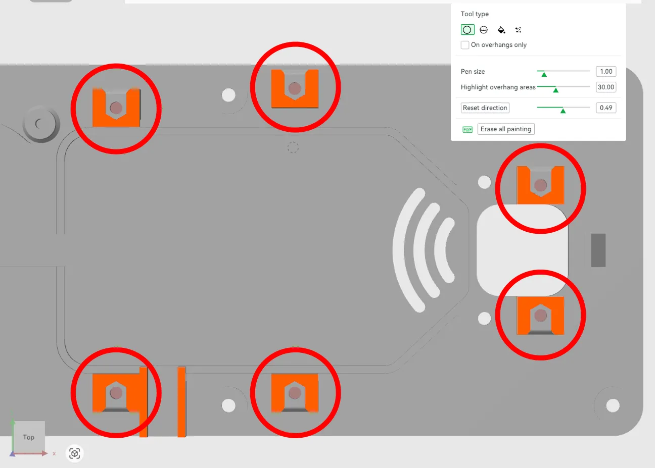
The baseplate has six nut pockets with cavities underneath. Support blockers have been manually painted inside these cavities to prevent support material from being generated there, as it would be very difficult to remove after printing. The support material in the nut pockets themselves is left in place and can be removed easily.
The image below shows the six cavities highlighted with red circles. The small red dots inside each cavity are the manually painted support blockers:
The image below shows the sliced result:
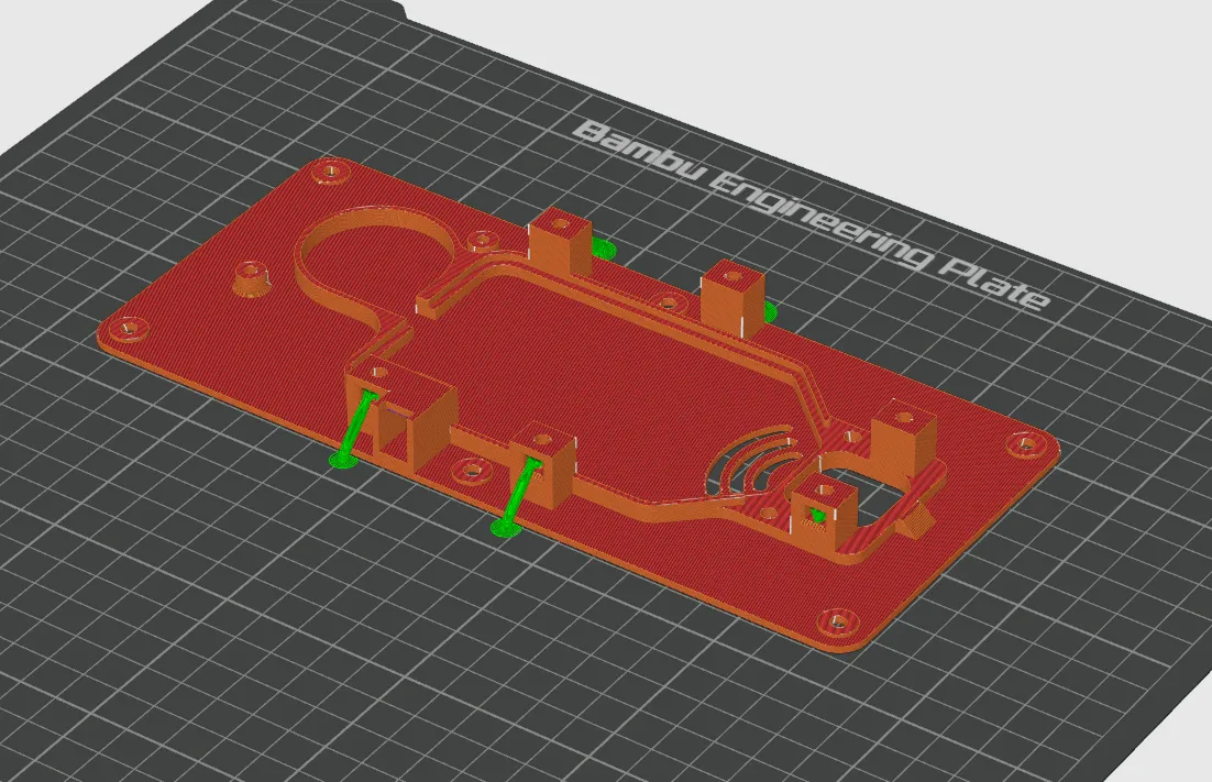
Do not remove or modify the support blockers in the 3MF file.
License & Disclaimer
CC BY-NC 4.0
All files on this page are licensed under CC BY-NC 4.0. You are free to download, print, share and adapt them, as long as you credit Filametric and do not use them for commercial purposes. Printing parts for your own personal or business use is permitted. Selling the files, printed parts, or using them to build competing products is not.
Disclaimer
These files are provided as-is. Modifications to the model, print settings or orientation may affect fit and function and are at your own risk. See our Terms of Use for more information.