Chapter 2: Preparing the housing
Chapter 3: Housing assembly
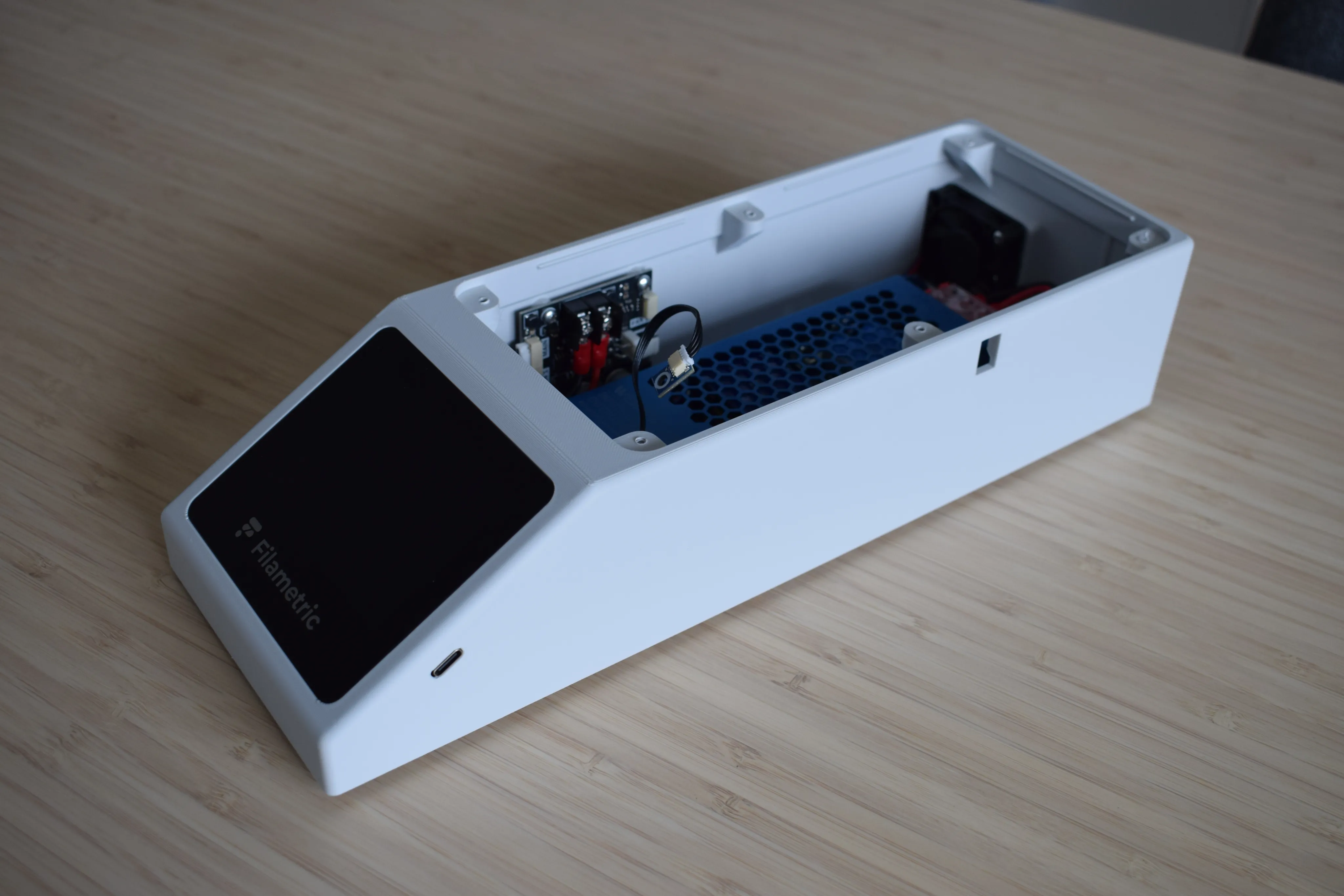
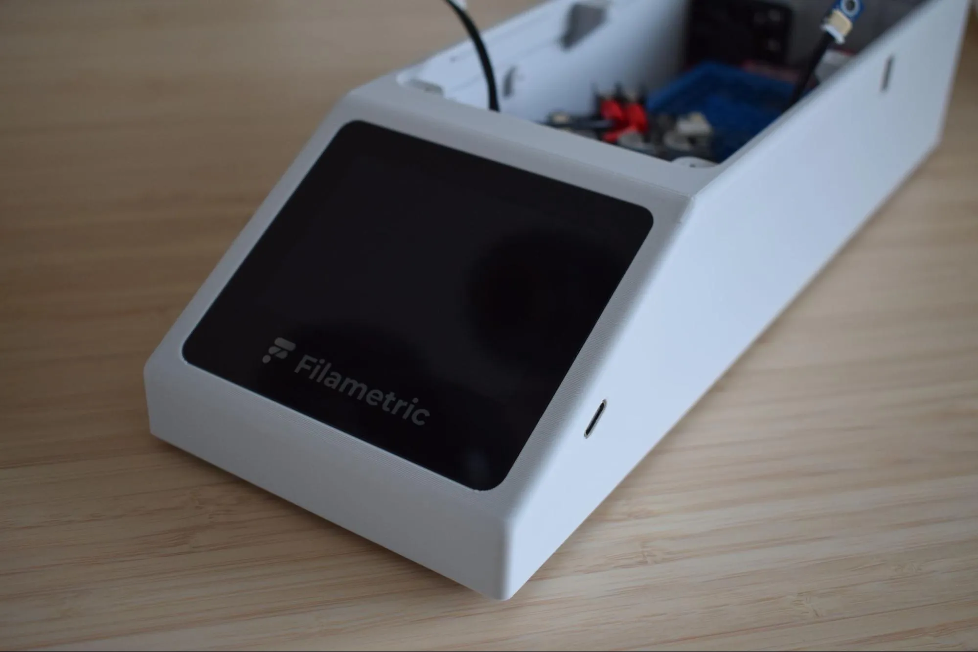
In this chapter you will assemble the housing, installing the power supply unit (PSU), exhaust fan, circuit boards, and display. This chapter takes roughly 60-90 minutes to complete. The result will look like the image below.
Step 1: Installing the C6 inlet
You will need:
- DryBase housing
- C6 inlet (from the Cables bag)
- Microfiber cloth
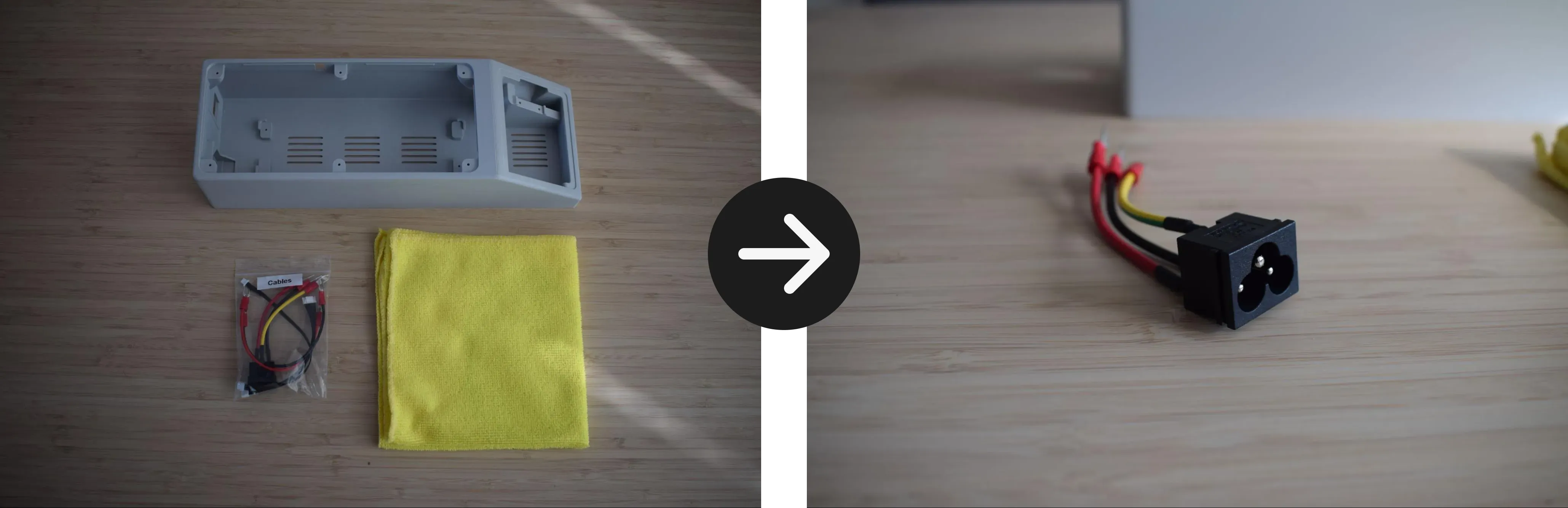
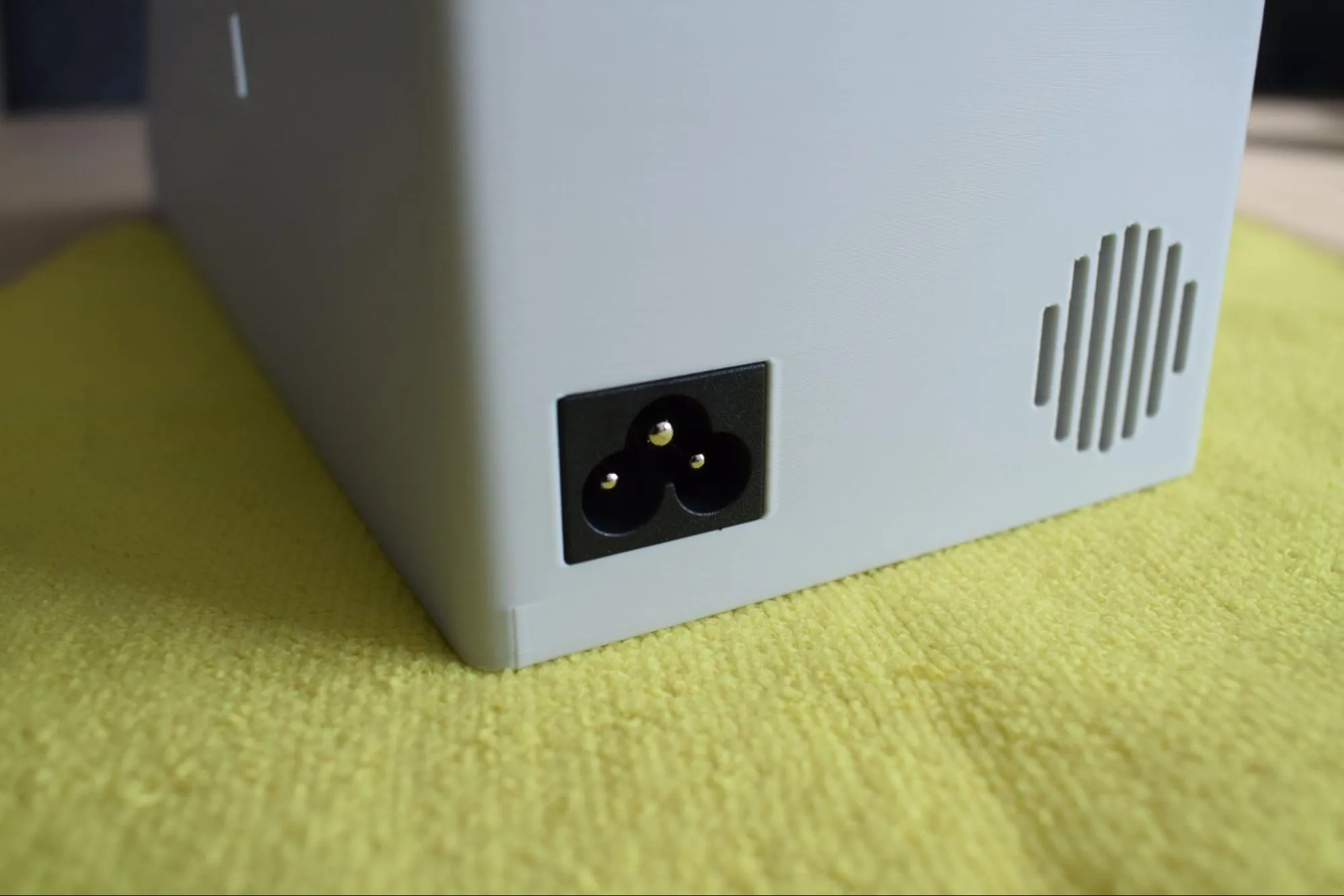
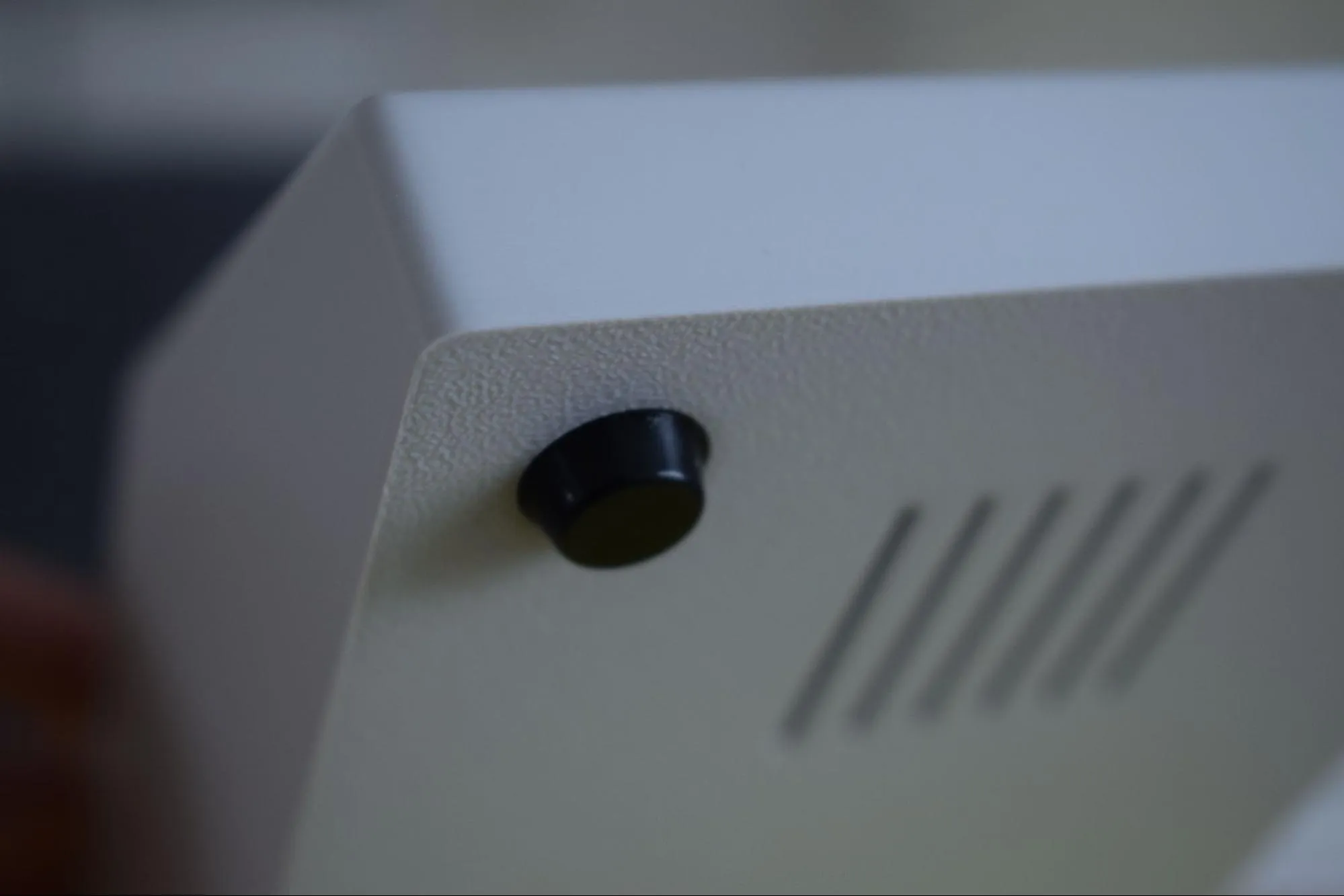
a. Locate the power socket opening at the back of the housing and insert the C6 inlet, aligning it flush with the left edge. Refer to the images below for the correct orientation.
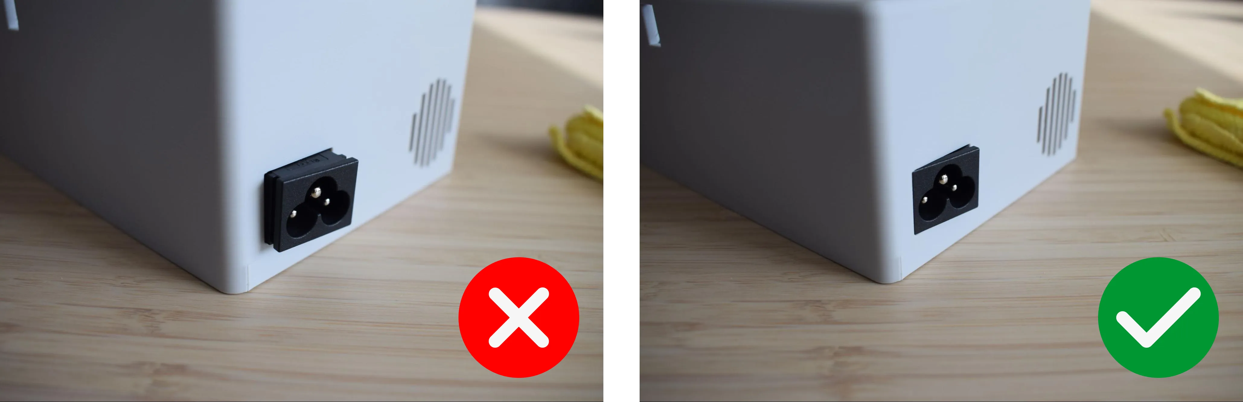
b. Stand the housing upright on the microfiber cloth with the back panel facing down. Then, apply firm downward pressure from the top until you hear and feel a clear snap. This confirms the inlet is seated.
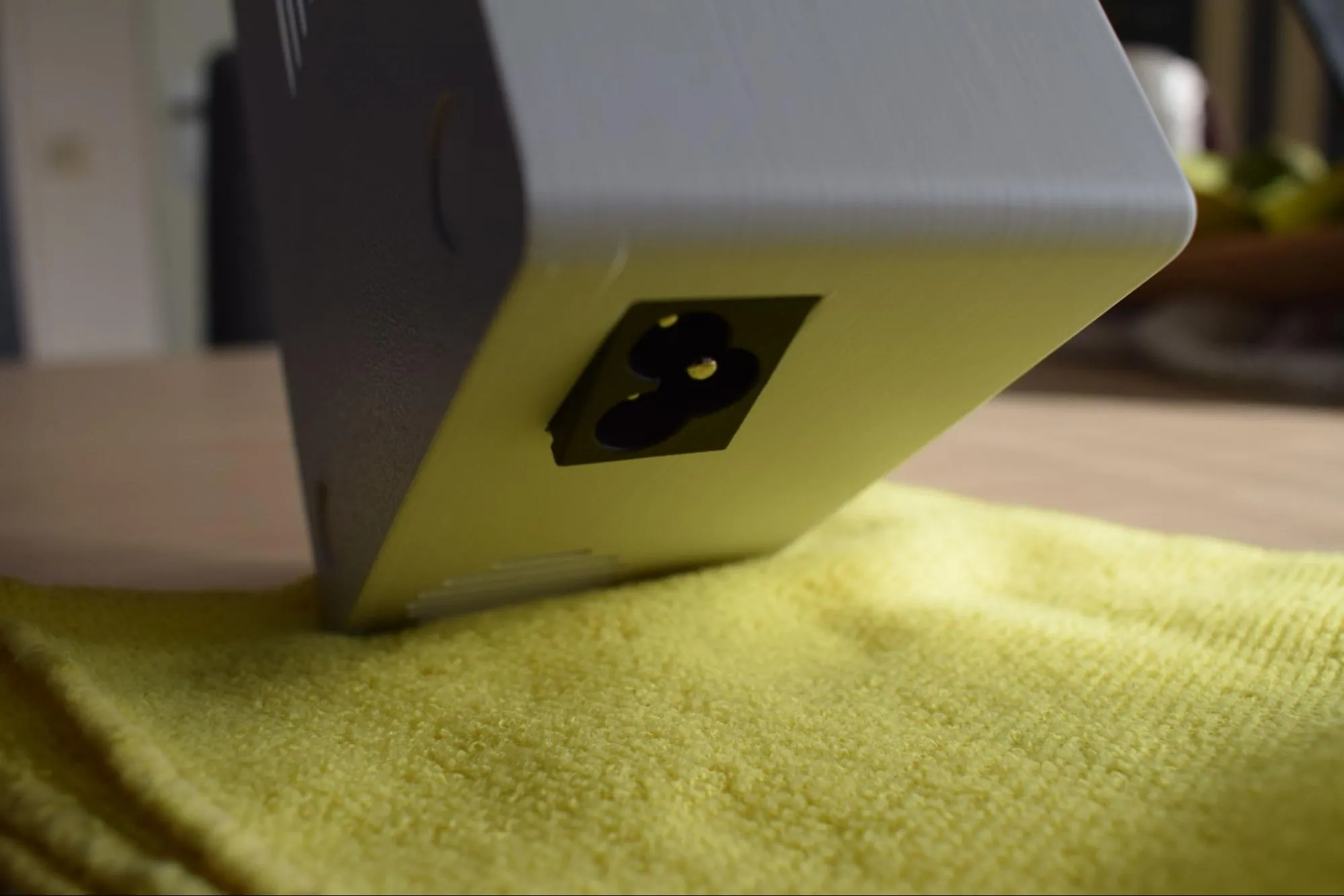
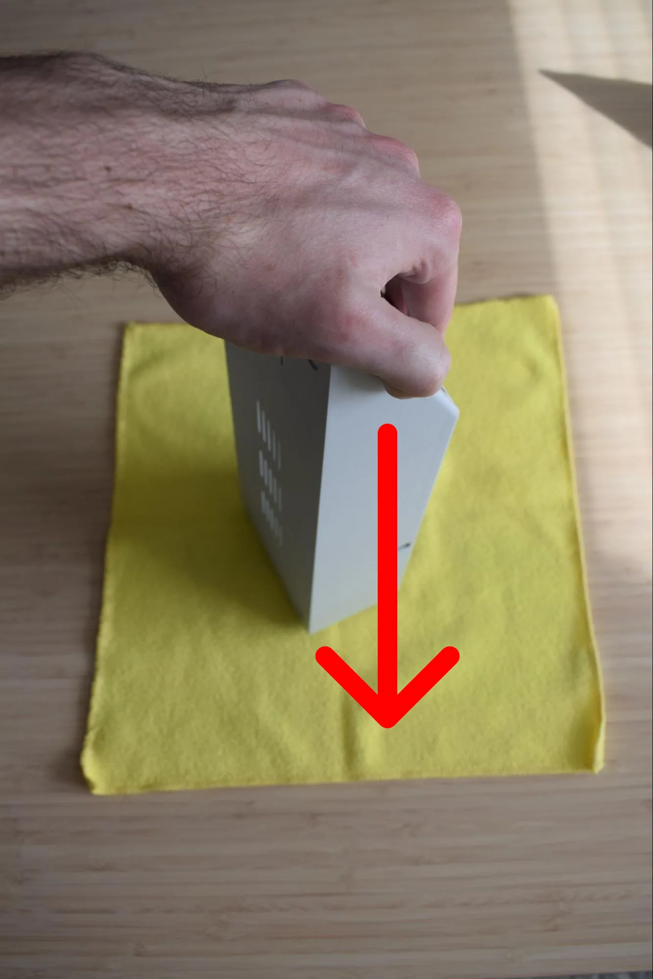
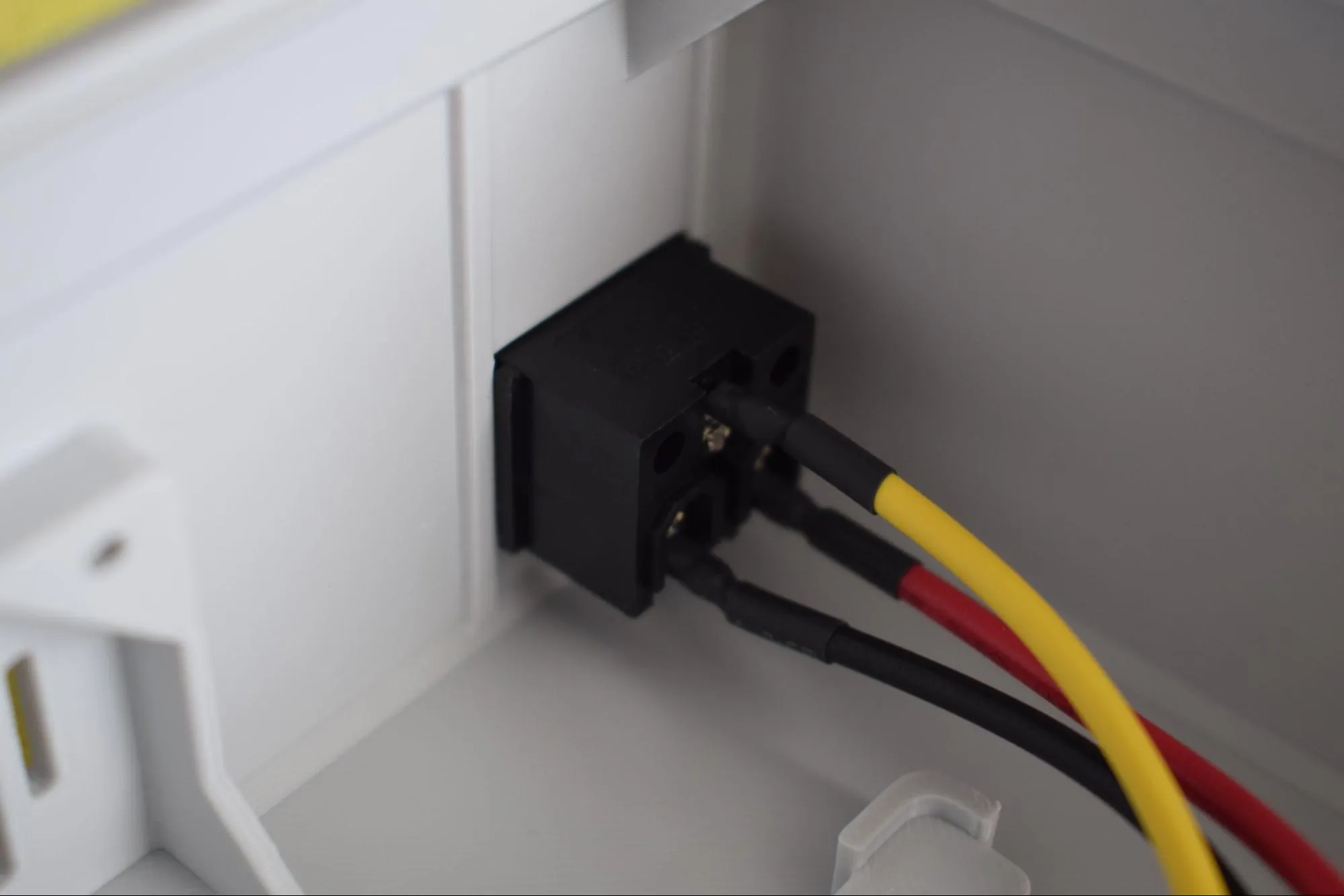
The images below show how the correctly installed inlet looks from the outside and the inside of the housing.
Check the snap
If you did not hear or feel a clear snap, the inlet may not be fully seated. Remove it and try again. A loose inlet can cause connection issues later.
Step 2: Installing the exhaust fan
You will need:
- Housing assembly (from the previous step)
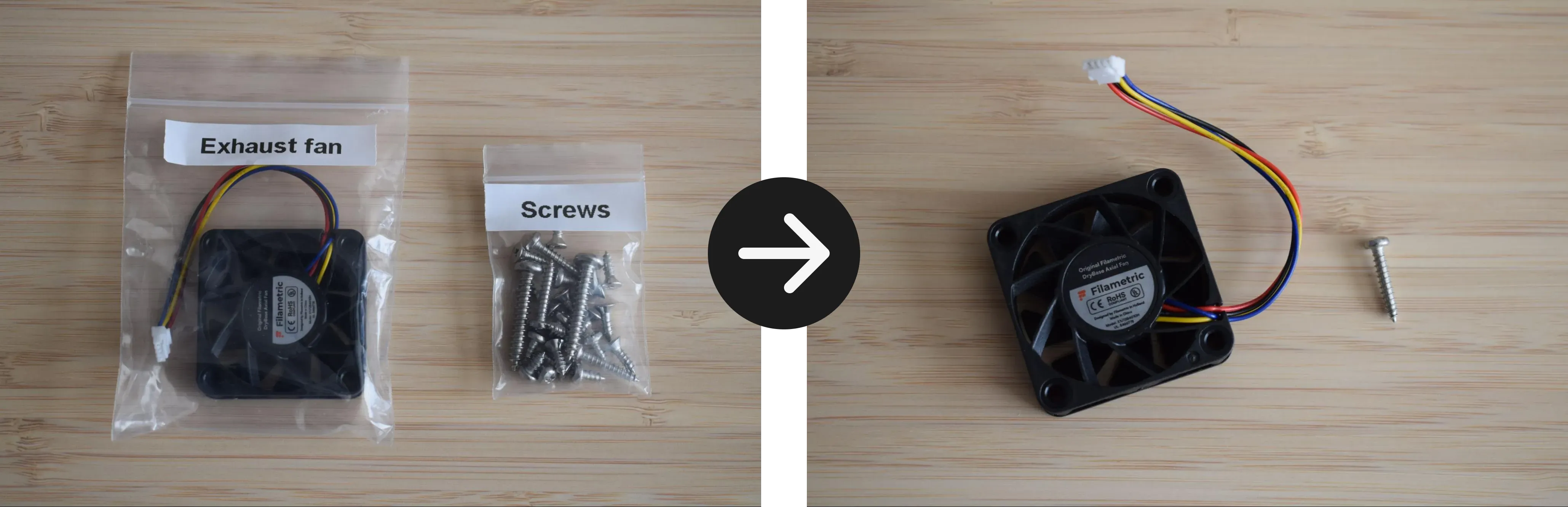
- Exhaust fan (from the Exhaust fan bag)
- 1x 2.9 x 16mm round-headed screw (DIN7981; from the Screws / Fasteners bag)
- Microfiber cloth
- Phillips screwdriver
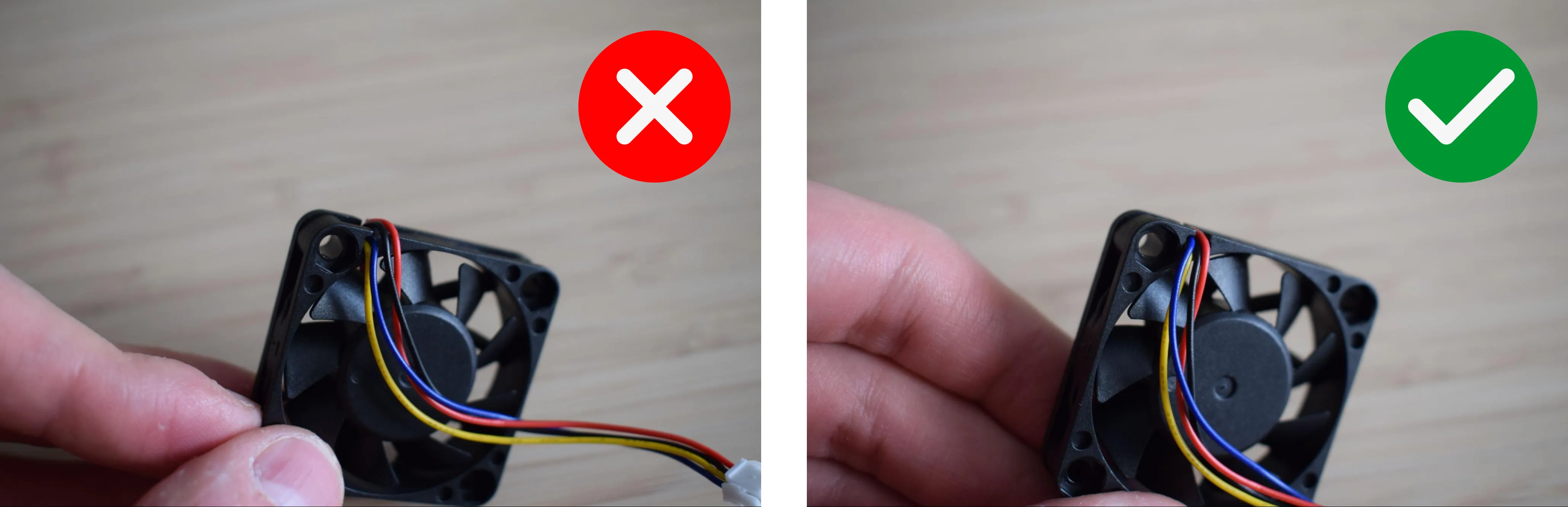
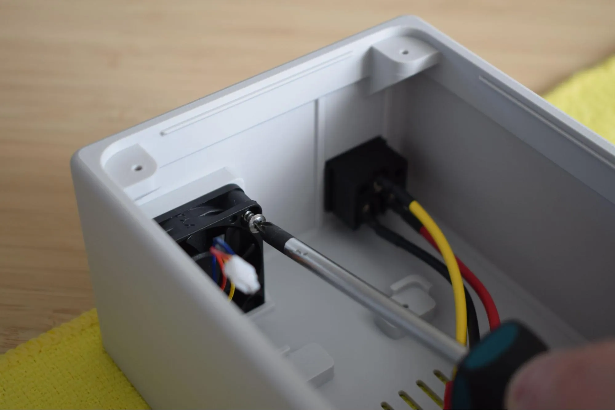
a. Before installing the fan, route its cable so it runs flat along the side of the fan housing, not sticking out from the front. The cable should be tucked neatly against the fan body, not protruding outward.
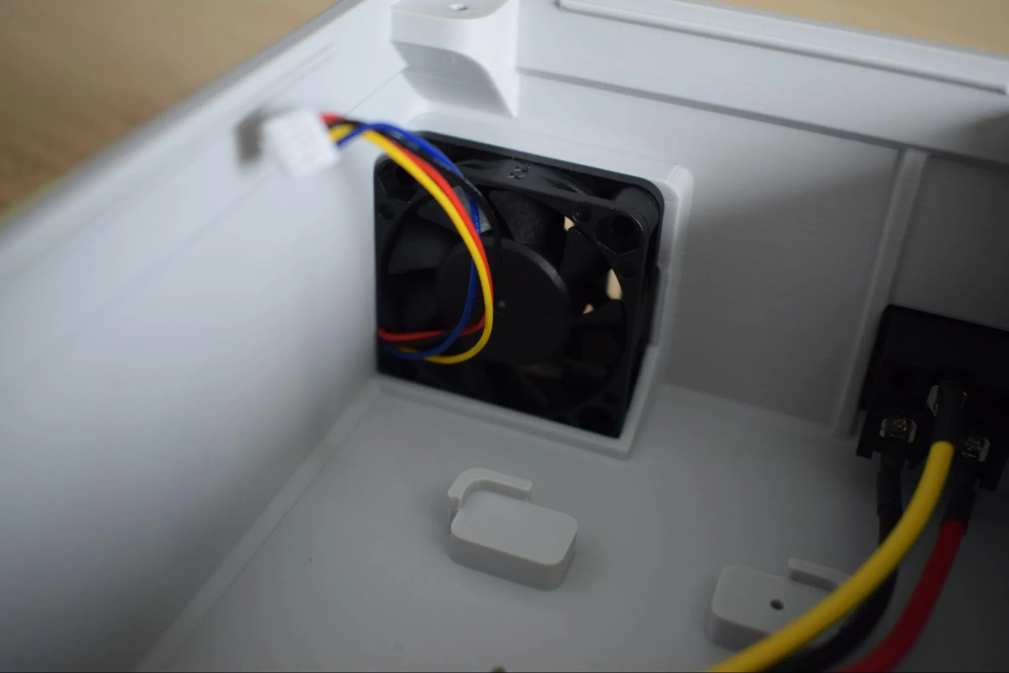
b. Press the fan into the dedicated pocket at the back of the housing. Inserting it at a slight angle first, then pushing it flat, makes this easier. Make sure the fan sticker is facing outward, towards the back of the housing.
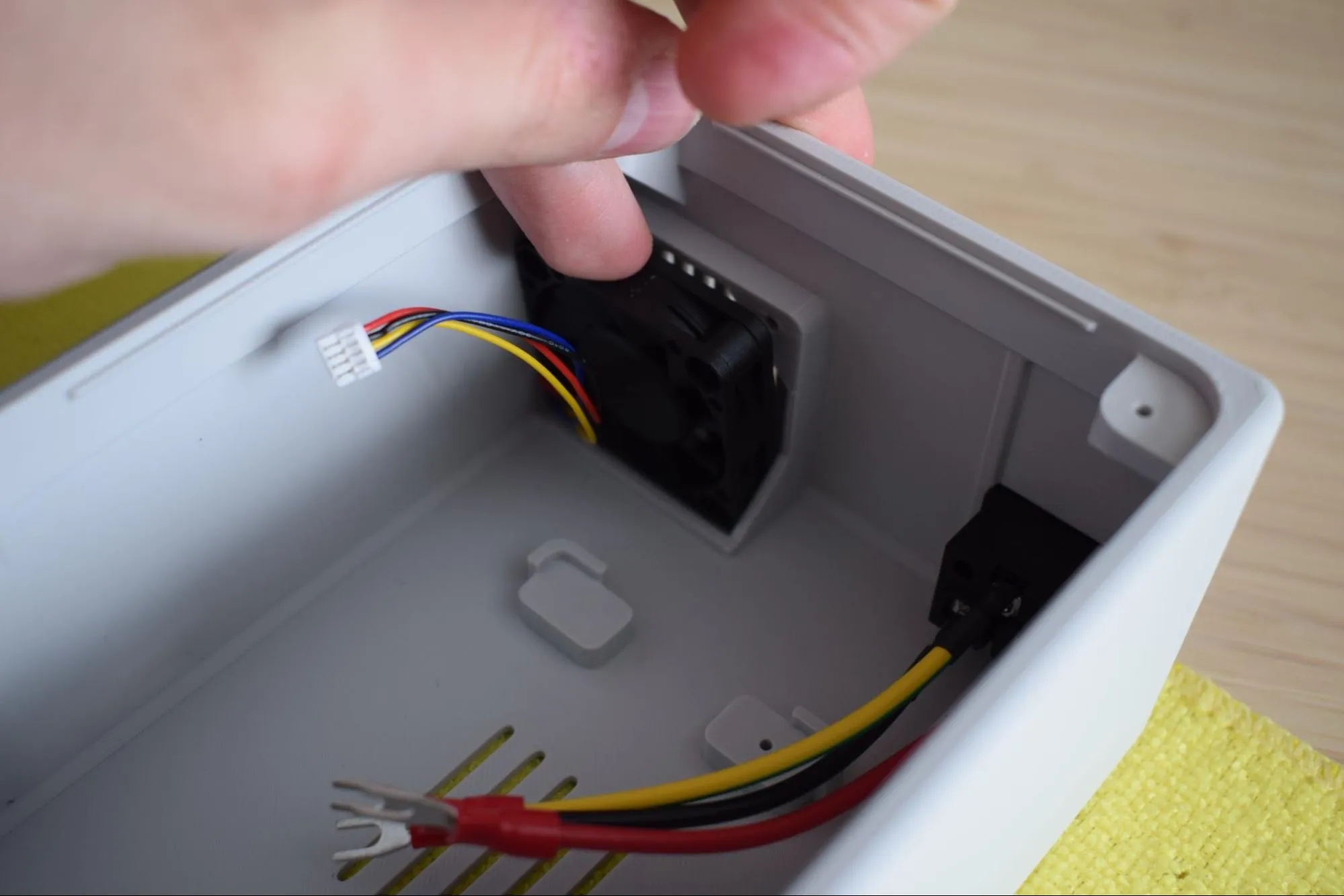
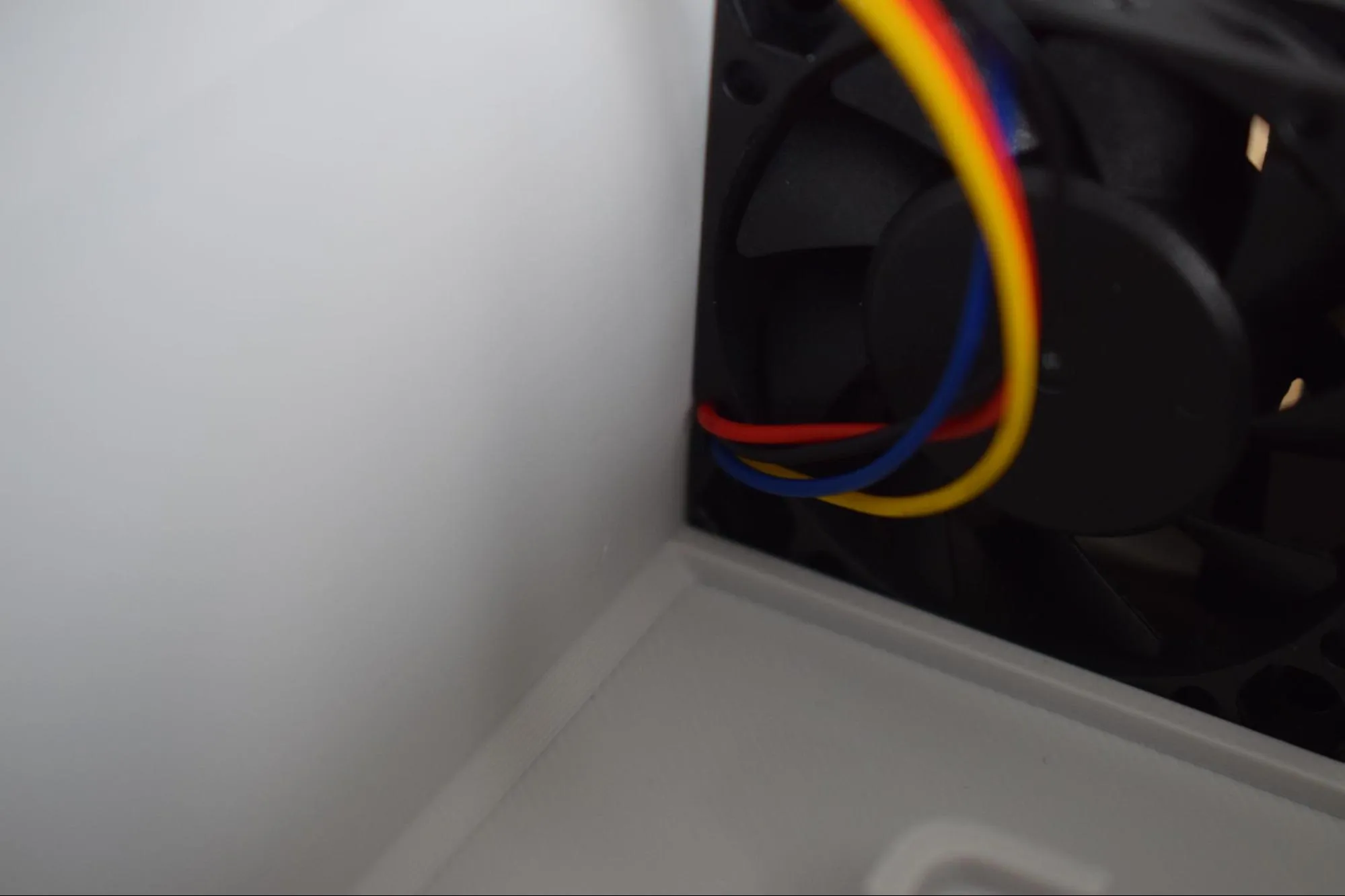
Once seated, ensure the cables are routed along the inside wall of the housing and are not pinched between the fan and the housing.
c. Secure the fan using the 2.9 x 16mm round-headed screw and your Phillips screwdriver.
Do not overtighten
The housing is 3D-printed and the material can crack or strip if too much force is applied. Stop as soon as the fan sits firmly in place.
Step 3: Connecting the power cables to the PSU
You will need:
- Power supply unit (PSU)
- 2x power cables with fork terminals (red & black) (from the Cables bag)
- Microfiber cloth
- Phillips screwdriver
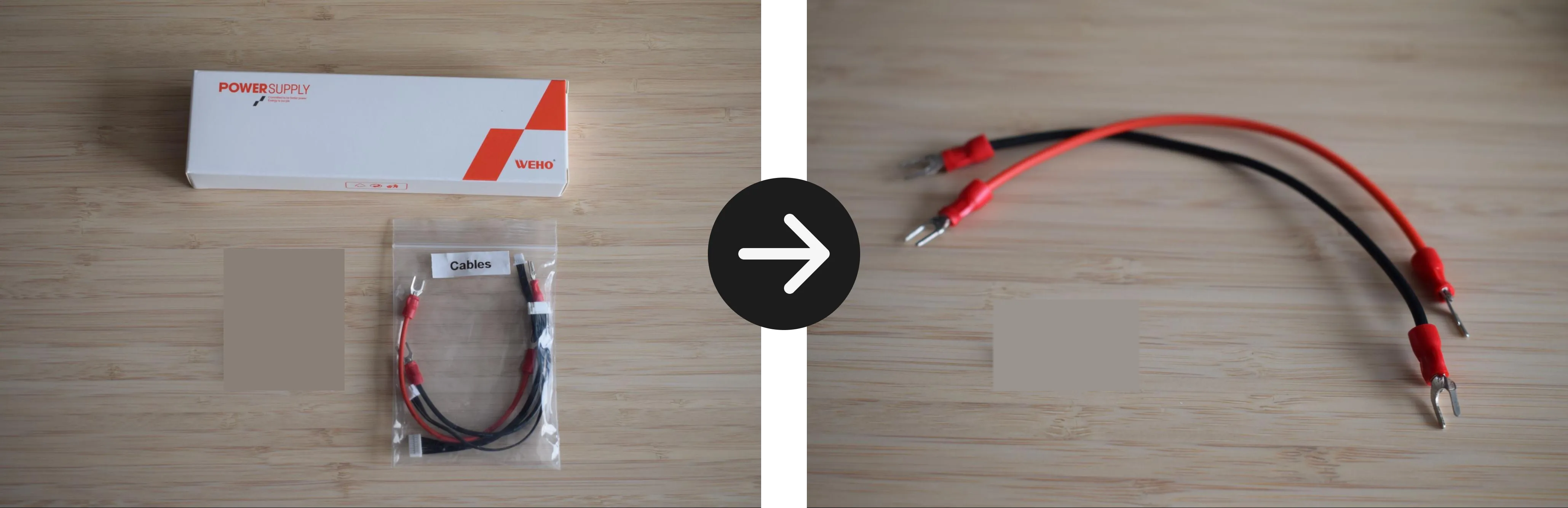
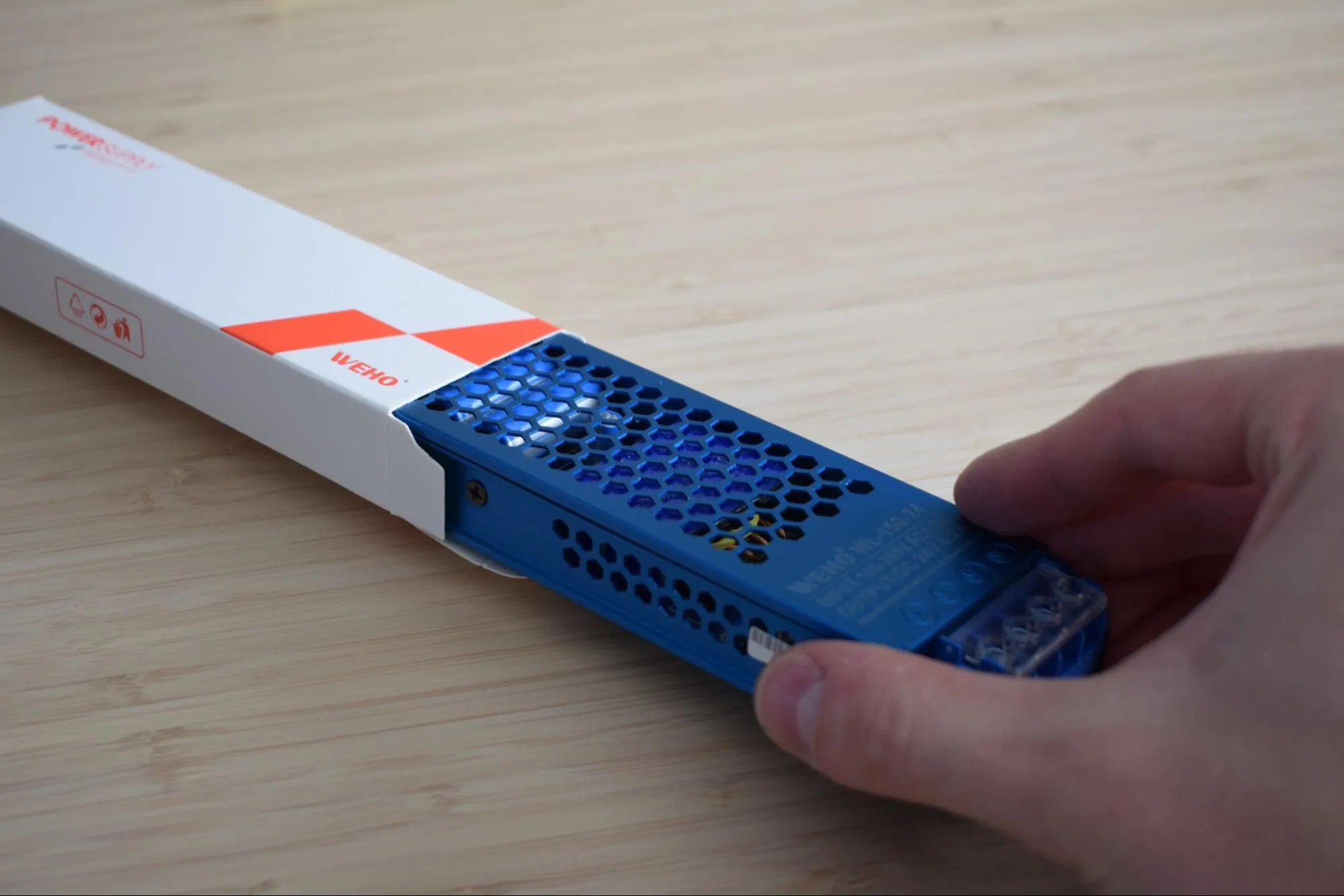
a. Remove the PSU from its packaging and inspect it for any visible damage before proceeding.
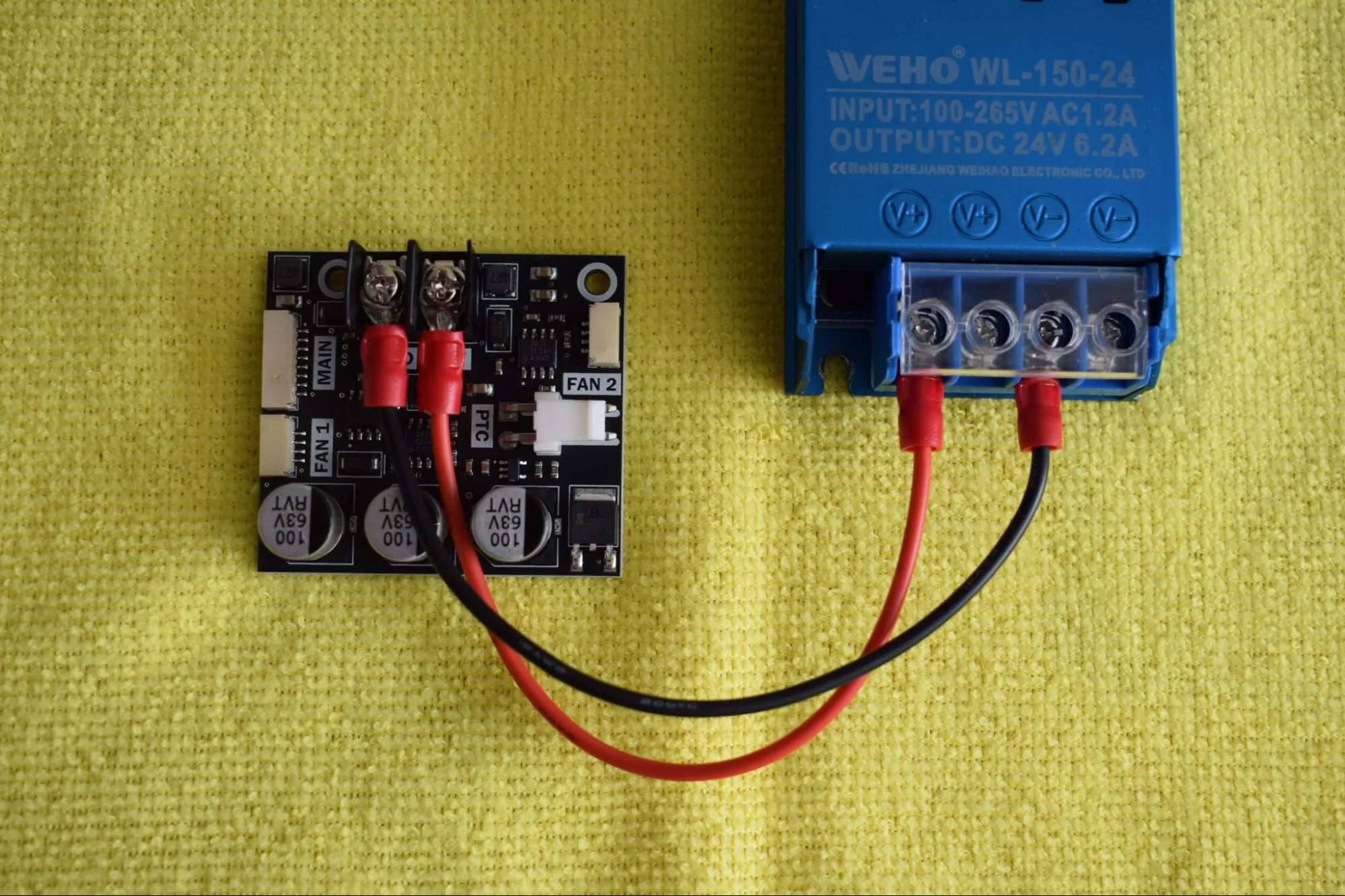
b. Locate the output terminal block on the PSU. The terminals are labeled from left to right: V+, V+, V-, V-. You will be connecting to terminals 1 and 3, as indicated by the red outlines in the image below. Loosen both terminal screws just enough to insert the fork terminals.
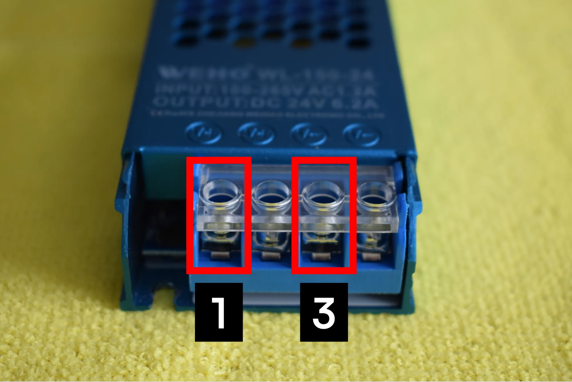
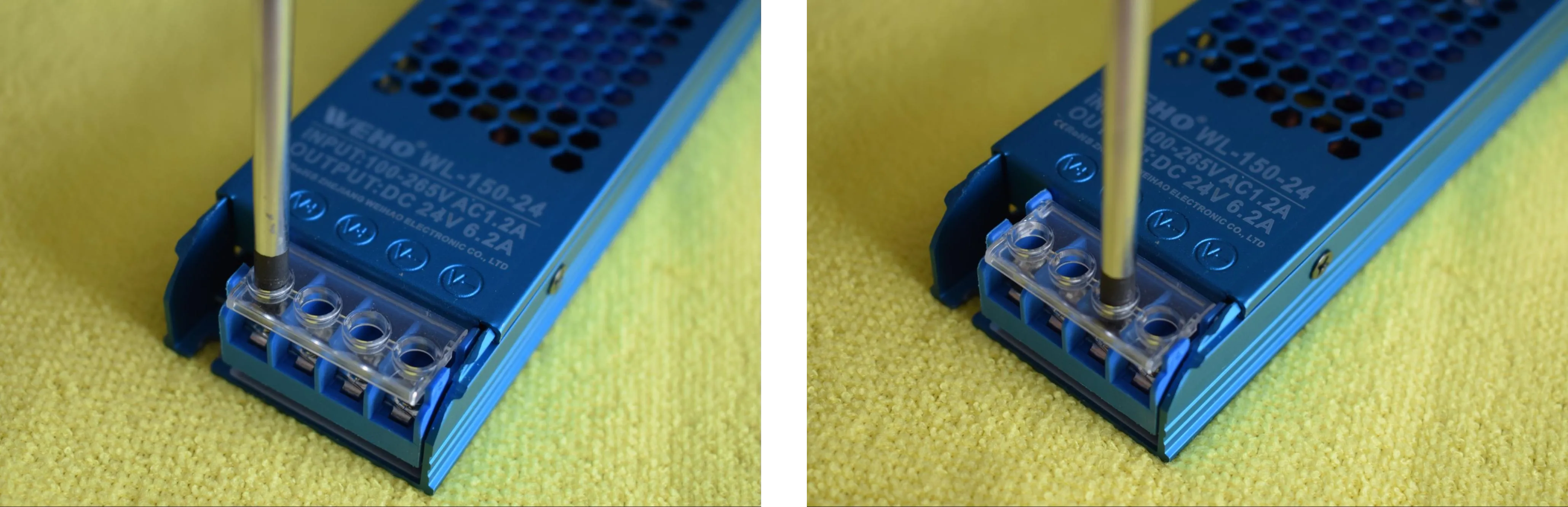
c. Insert the cables into the terminal block:
- Red wire to the first V+ terminal (position 1)
- Black wire to the first V- terminal (position 3)
Polarity is critical
Reversing the red and black wires will damage the DryBase electronics. Double-check before tightening.
d. Tighten both terminal screws securely. Give each wire a gentle tug to confirm it is properly seated and cannot be pulled out.
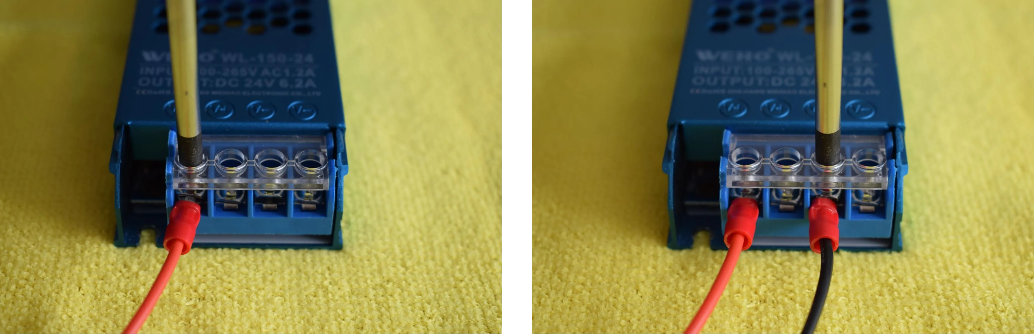
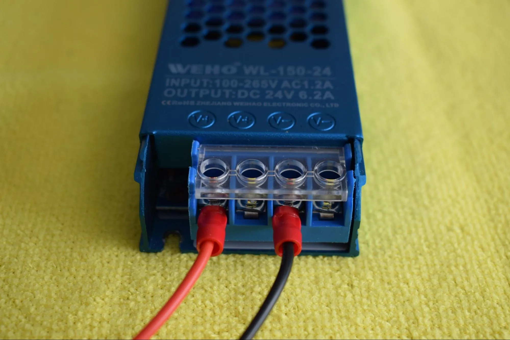
e. Confirm that the final result matches the image below: the red wire seated in the first V+ terminal and the black wire in the first V- terminal, with both screws tightened and the remaining terminals left empty.
Step 4: Connecting the PSU to the power board
You will need:
- Power supply + attached cables (from the previous step)
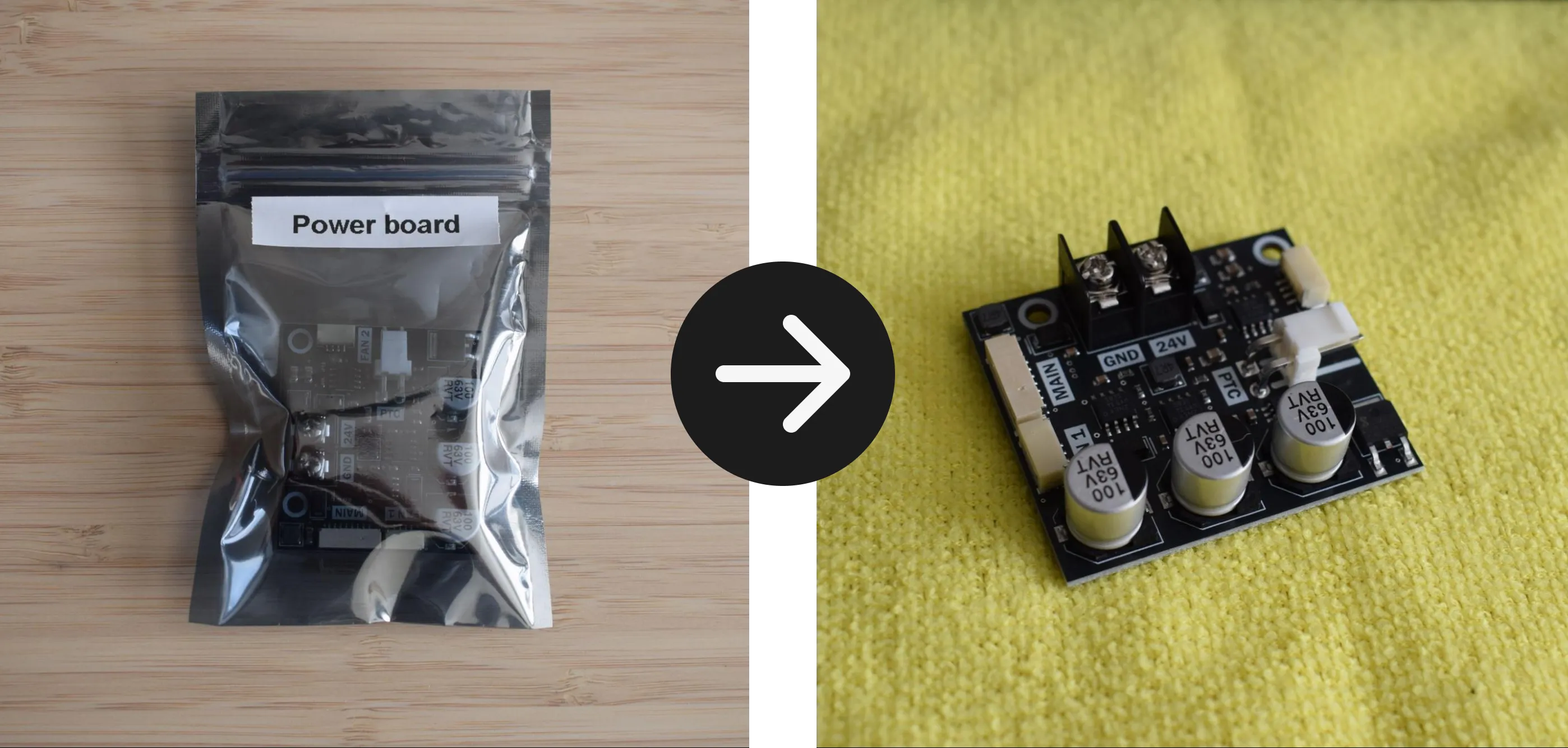
- Power board (from the Power board bag)
- Microfiber cloth
- Phillips screwdriver
a. Unpack the power board from its anti-static bag and place it on the microfiber cloth.
b. Locate the two screw terminals on the power board, labeled GND and 24V. Loosen both terminal screws using your Phillips screwdriver, just enough to insert the fork terminals.
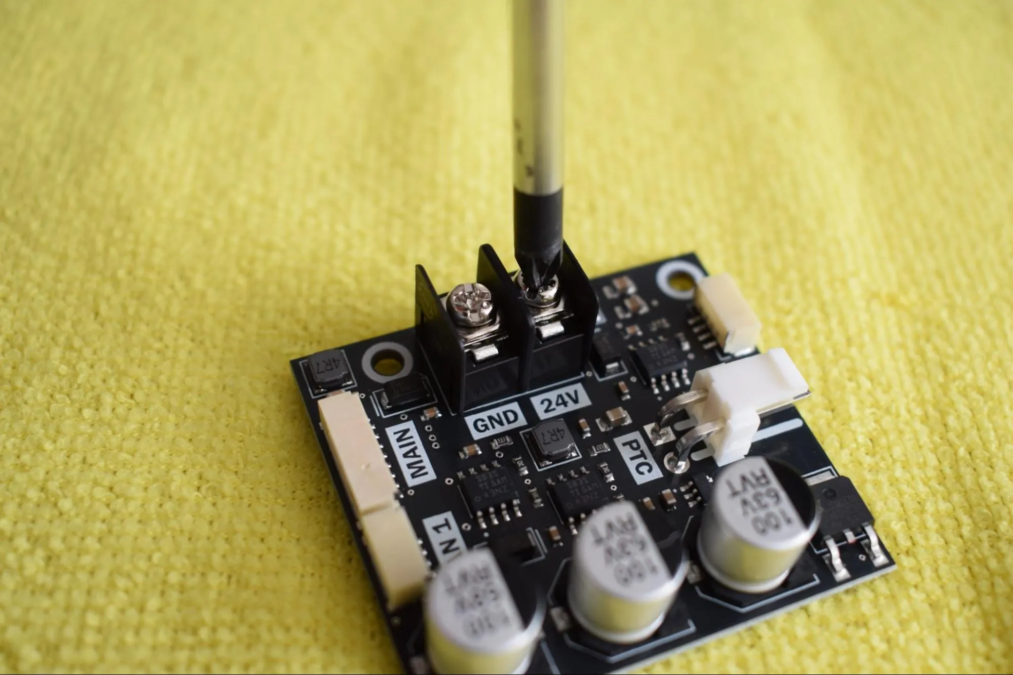
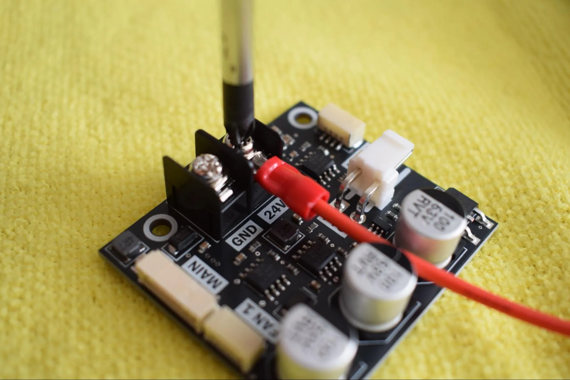
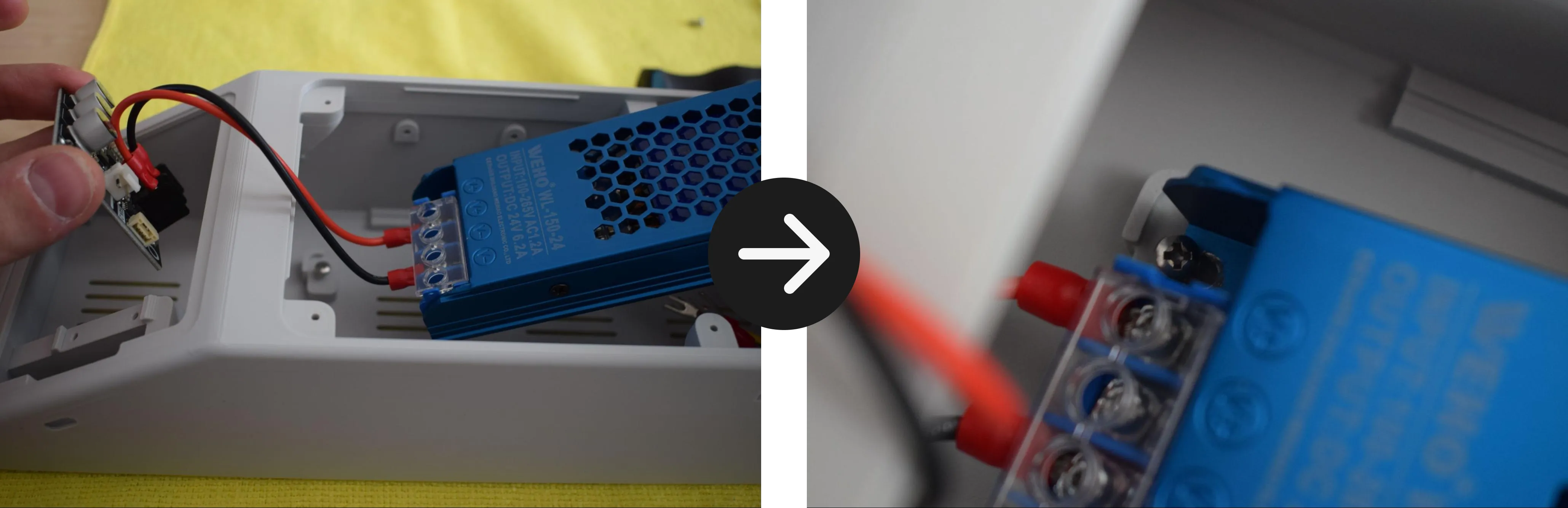
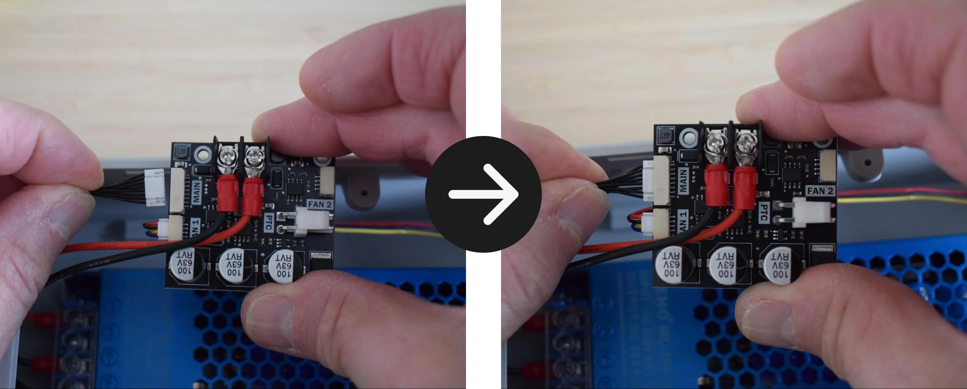
c. Insert the red wire into the 24V-labeled terminal. Make sure the wire runs downward as shown in the image below.
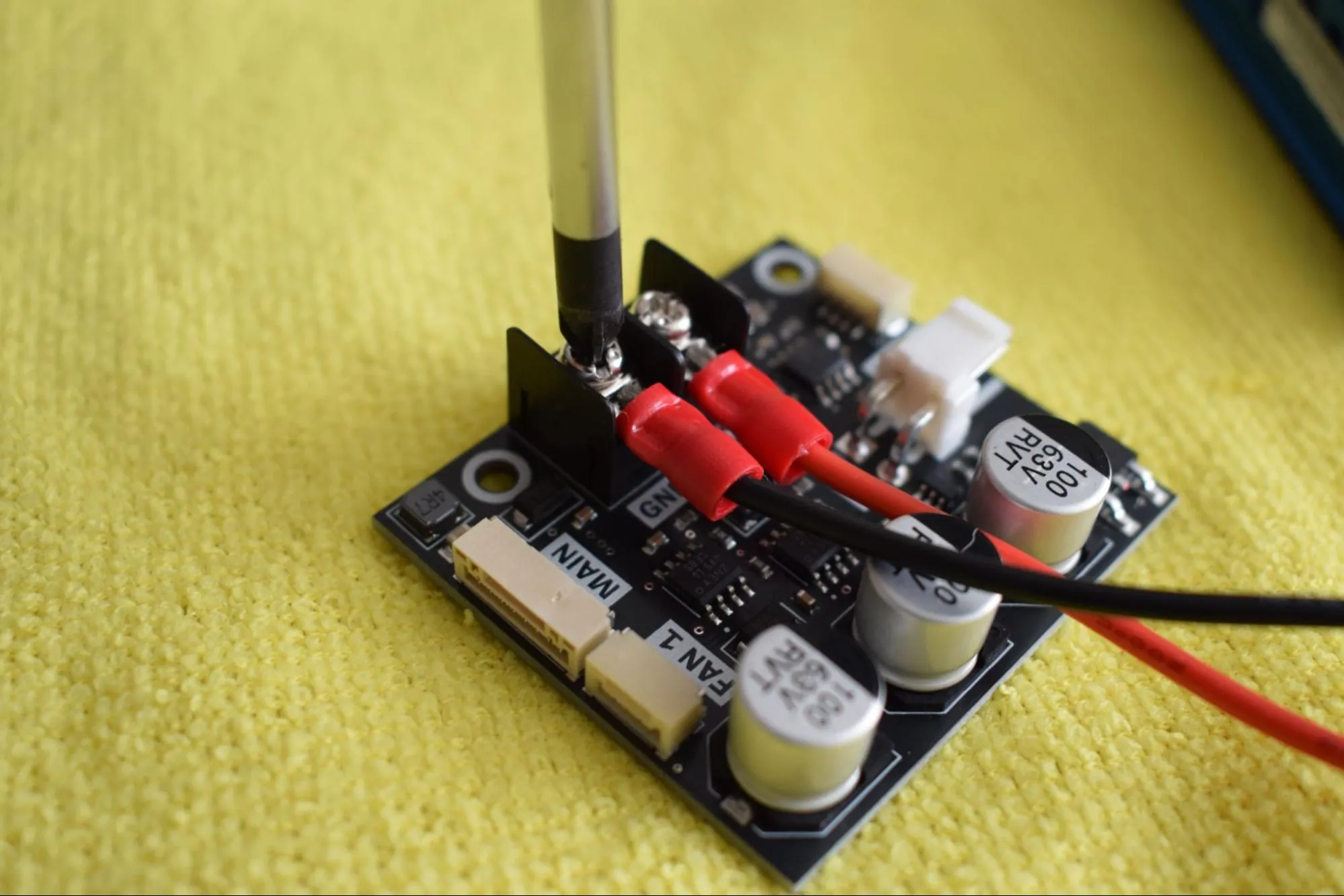
d. Insert the black wire into the GND-labeled terminal. Make sure the wire runs downward in the same direction as the red wire.
Polarity is critical
Red must go to 24V and black to GND. Reversing the wires will damage the power board and other electronics. Double-check before tightening.
e. Tighten both terminal screws securely and give each wire a gentle tug to confirm it is properly seated. Confirm that the final result matches the image below.
Step 5: Installing the PSU into the housing
You will need:
- Housing assembly (from a previous step)
- Power supply + attached cables & power board (from the previous step)
- 2x 2.9 x 6.5mm round-headed screws (DIN7981; from the Screws / Fasteners bag)
- Microfiber cloth
- Phillips screwdriver
a. Place the housing on the microfiber cloth with the open side facing up. Drive a 2.9 x 6.5mm round-headed screw into the front mounting hole as shown in the image below, leaving 2-3mm of spacing between the screw head and the housing. This acts as a rail to slide the PSU under.
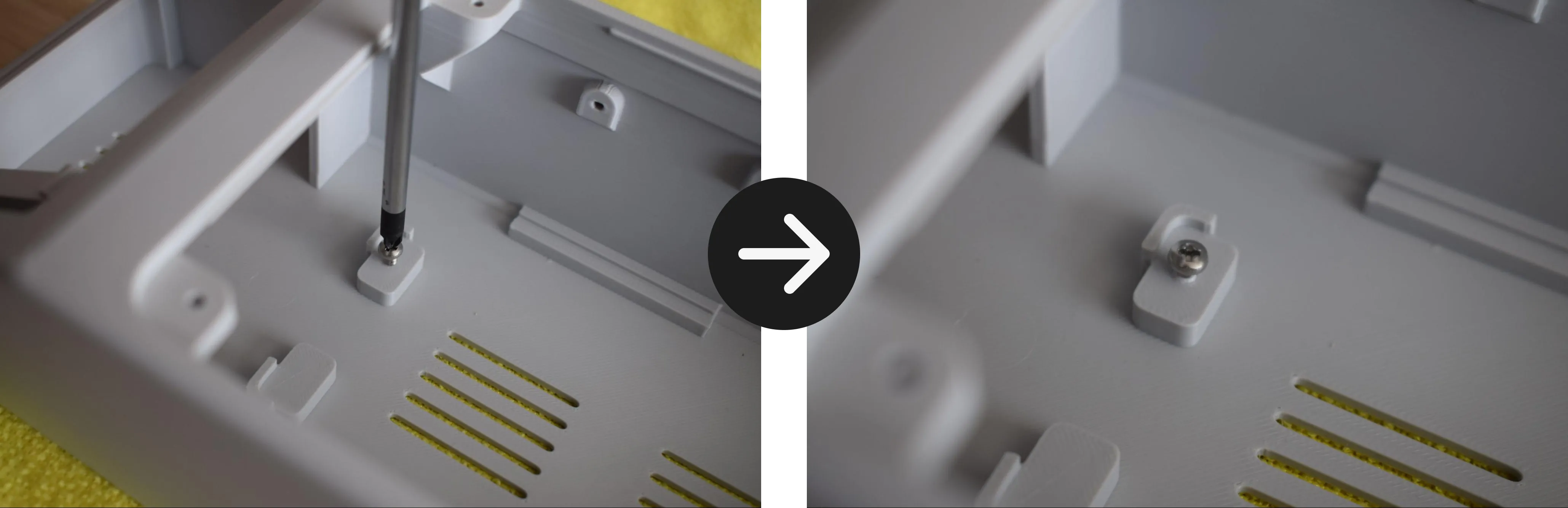
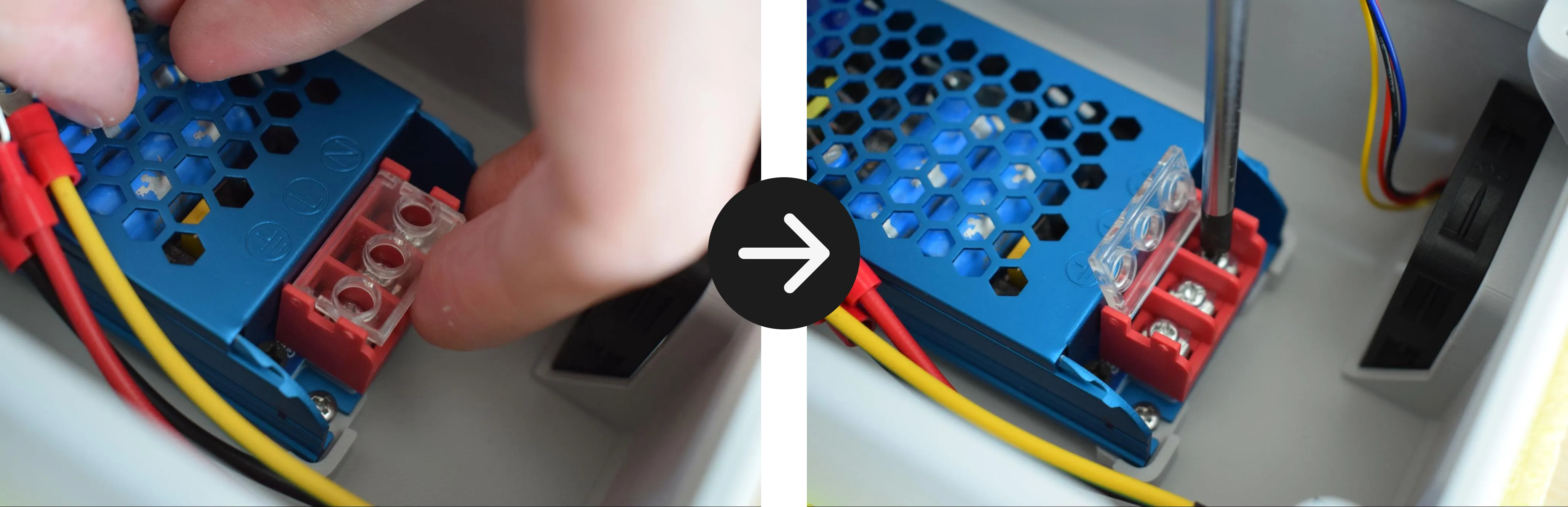
b. Hold the power board in your left hand and the PSU in your right hand. Tilt the PSU at a slight angle and slide the front edge underneath the partially tightened screw, as shown in the images below.
c. Once the front of the PSU is seated under the screw, lower the back of the PSU down into the housing until it sits flat, as shown in the image below.
d. Tighten the front screw to secure the PSU in place.
Do not overtighten
The housing is 3D-printed and the material can crack or strip if too much force is applied. Stop as soon as the PSU sits firmly in place.
e. Drive the second 2.9 x 6.5mm round-headed screw into the back mounting hole to fully secure the PSU.
f. Rest the power board in the housing as shown in the image below. It will be secured in a later step.
Step 6: Connecting the C6 inlet and exhaust fan
You will need:
- Housing assembly (from the previous step)
- Microfiber cloth
- Phillips screwdriver
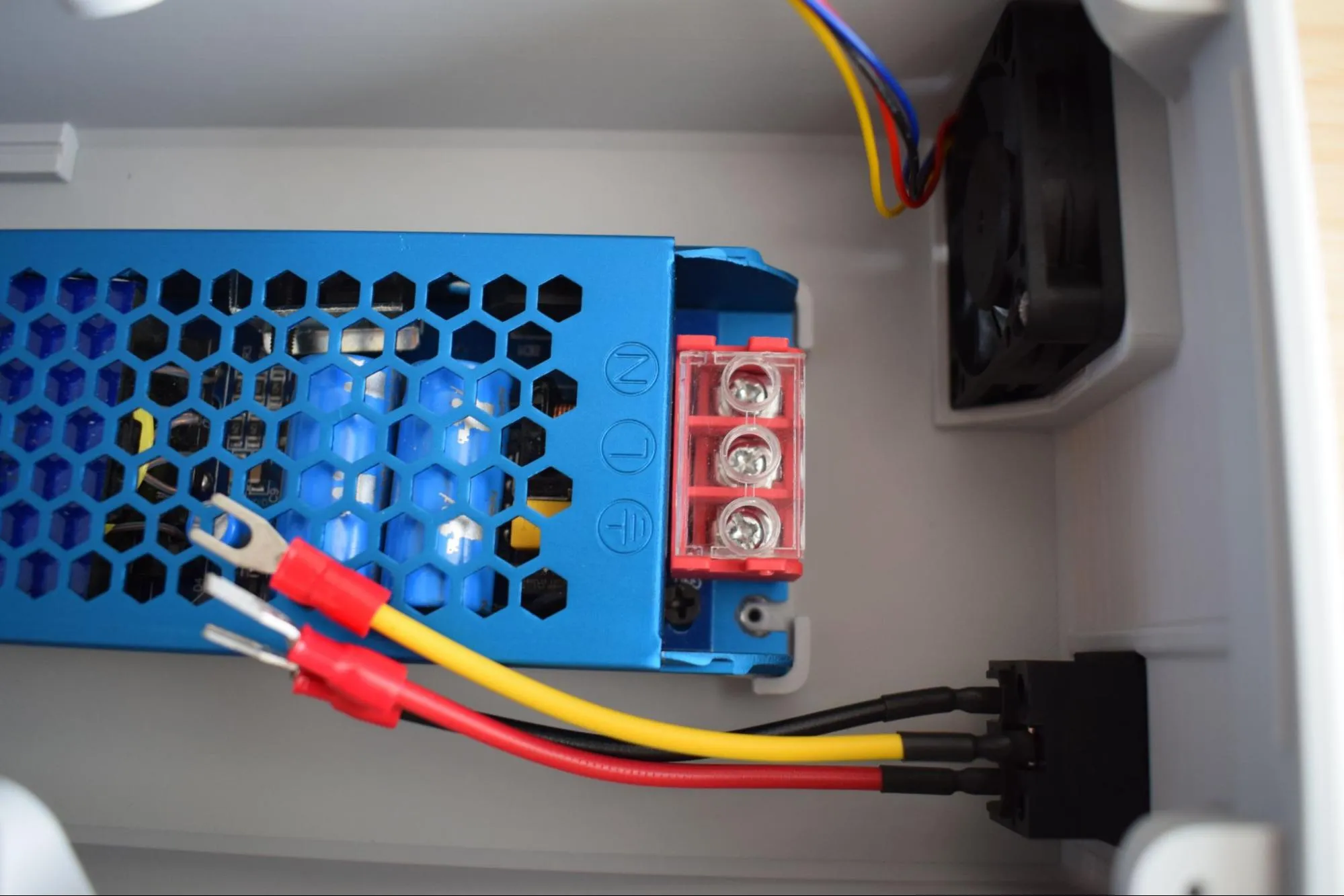
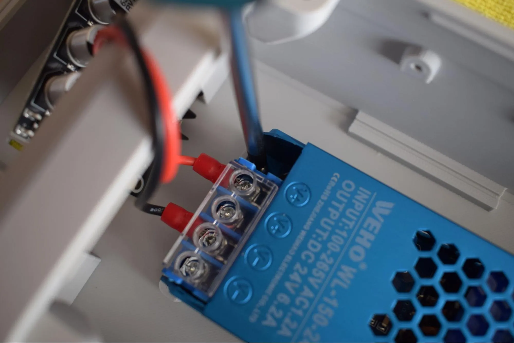
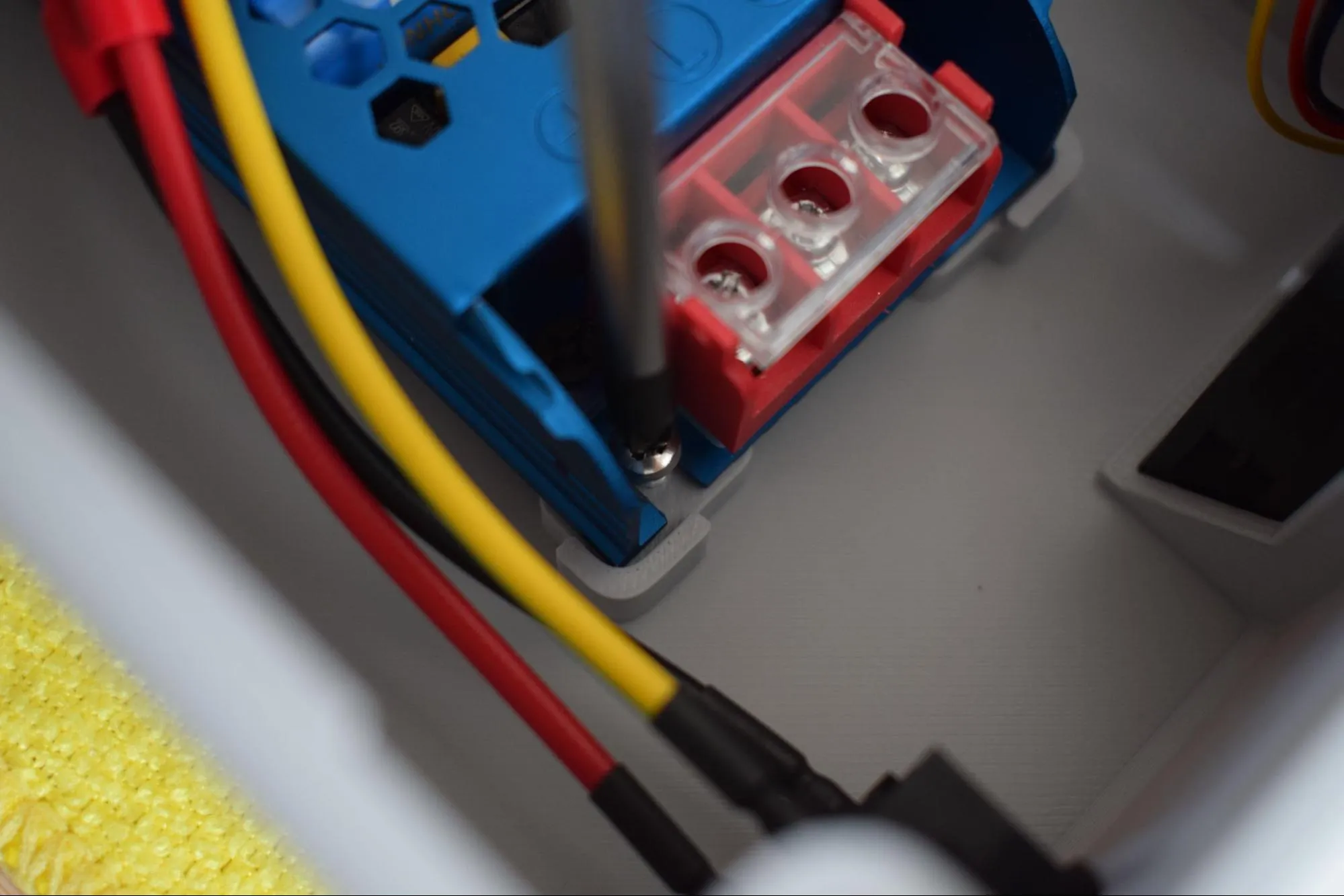
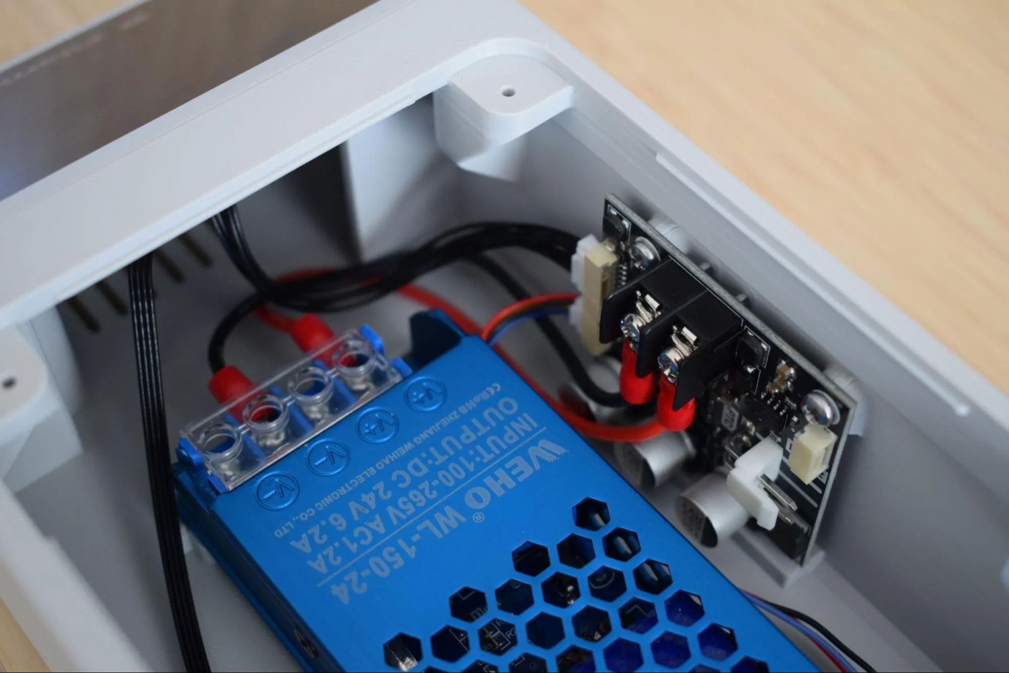
a. Locate the AC input terminal block on the back side of the PSU (these are the terminals not yet connected). Lift the transparent plastic cover to access them, then loosen all three terminal screws to allow the fork terminals to fit in.
b. Insert the three wires from the power socket into the terminal block in the correct order.
- Yellow/green wire to the left terminal (⏚ - Ground)
- Red wire to the middle terminal (L - Live)
- Black wire to the right terminal (N - Neutral)
Safety warning
This terminal block connects directly to mains voltage. Double check all three wire positions before tightening. Incorrect wiring can cause permanent damage or create a safety hazard.
c. Tighten all three terminal screws securely, then close the transparent plastic cover. Give each wire a gentle tug to confirm the fork terminals are fully secured and cannot be pulled loose.
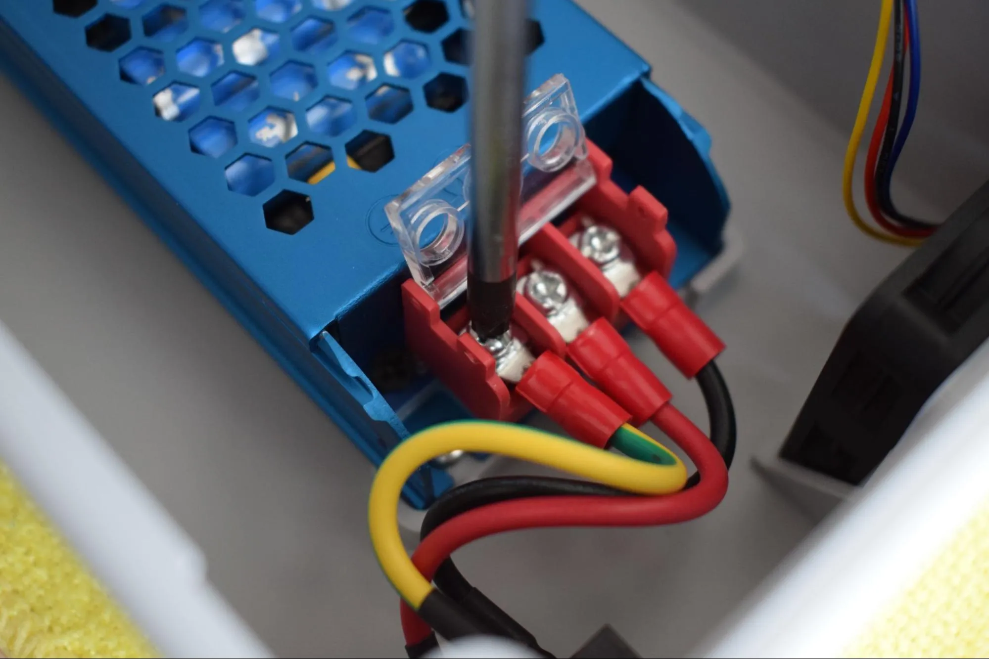
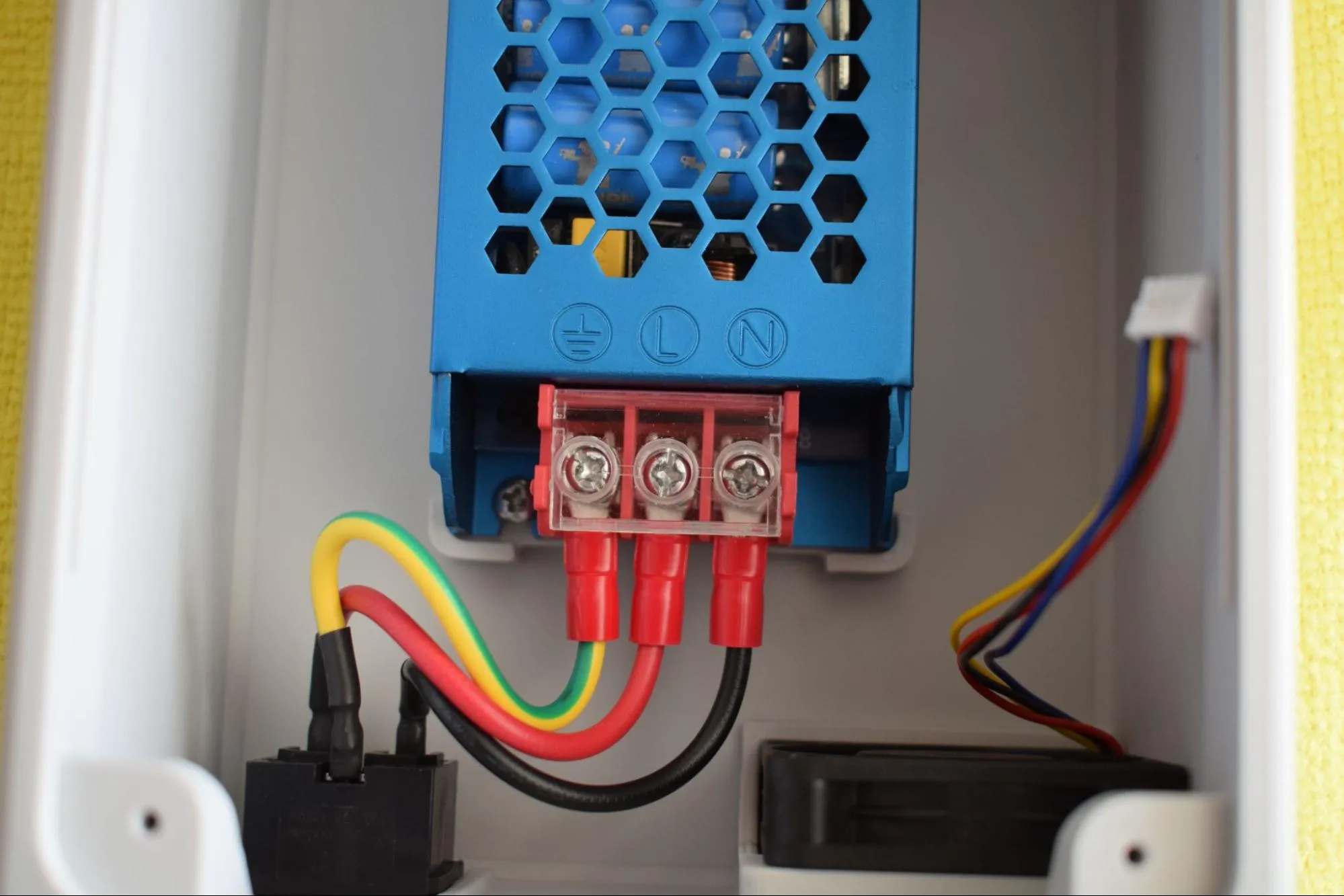
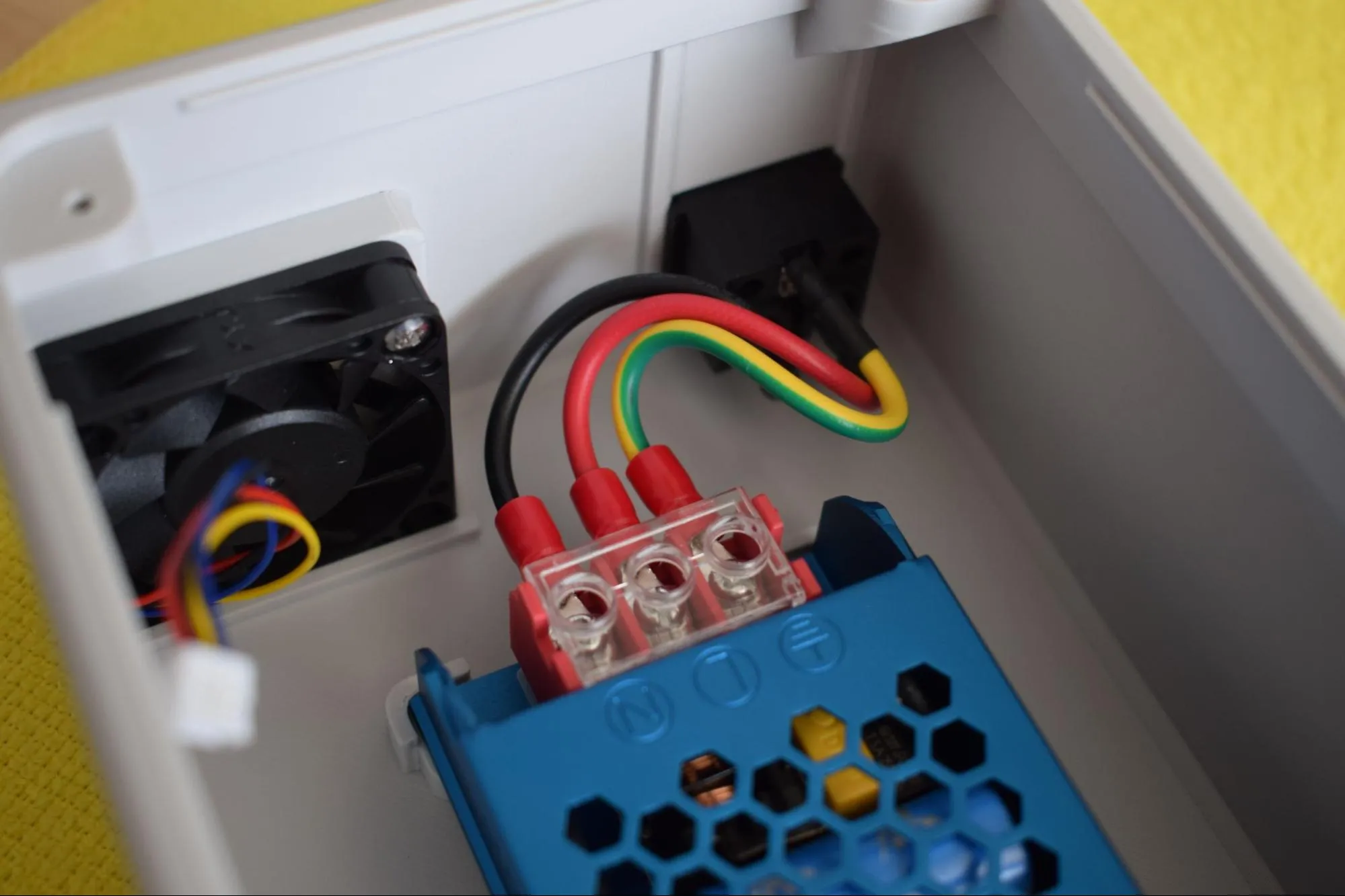
d. Verify that the wiring matches the image below. Check both the wire routing and polarity from the front view before continuing.
e. Connect the exhaust fan cable to the connector labeled FAN 1 on the power board. A clear click should be heard and felt when the connector is fully seated. Give the cable a gentle tug to confirm it is secure. Place the power board back in its position in the housing. It will be fully secured in a later step.
Step 7: Placing the rubber feet
You will need:
- Housing assembly (from the previous step)
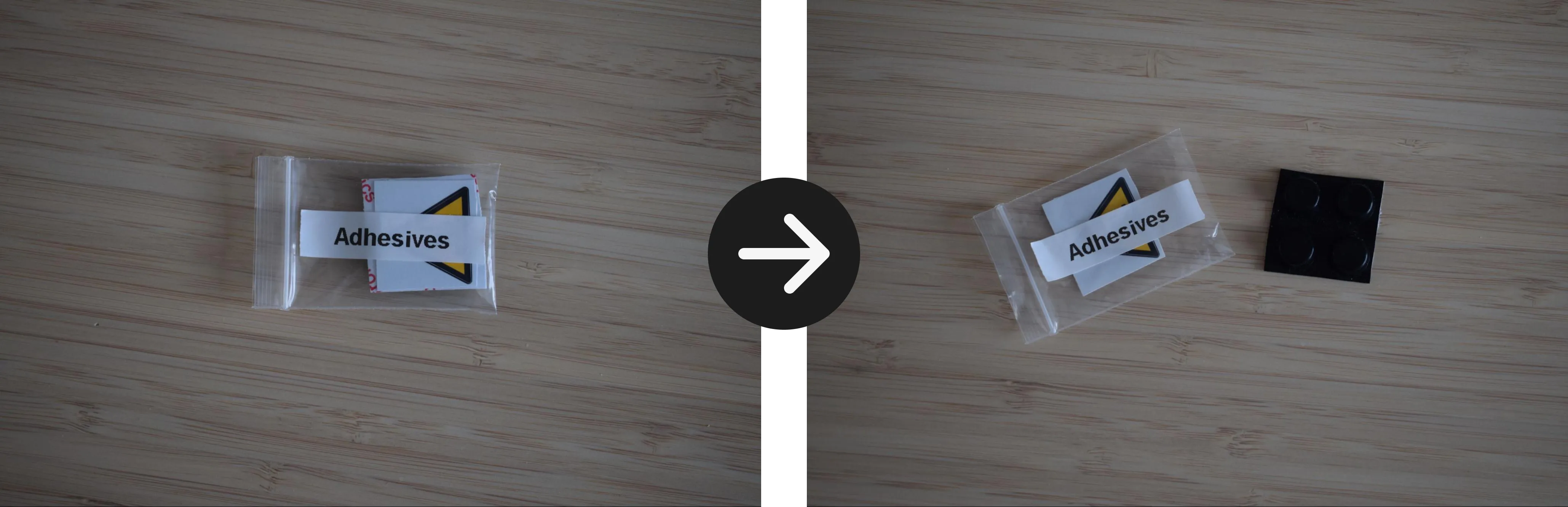
- 4x rubber feet (from the Adhesives bag)
a. Remove the strip of 4 rubber feet from the Adhesives bag.
b. Press one rubber foot into each of the four corner cavities at the bottom of the housing.
Be mindful of the power board
The power board is not yet secured to the housing and can shift during handling.
Step 8: Connecting the display and Main & Sensor board
You will need:
- Housing assembly (from the previous step)
- Main & Sensor board (from the Main & Sensor board bag)
- Main & Sensor board cables (from the Cables bag)
- Display (from the Display bag)
- Microfiber cloth
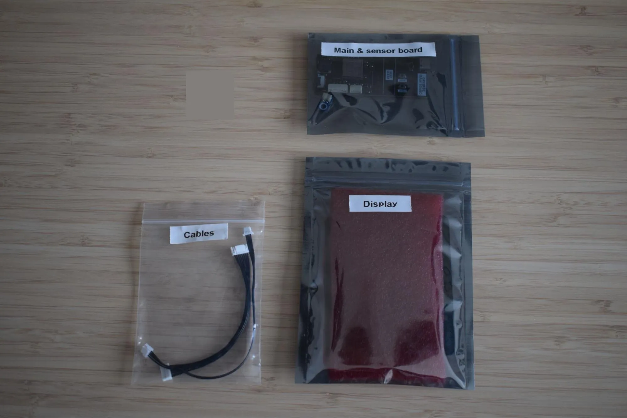
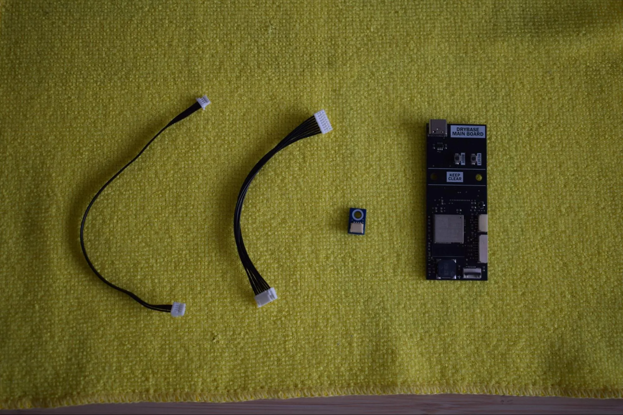
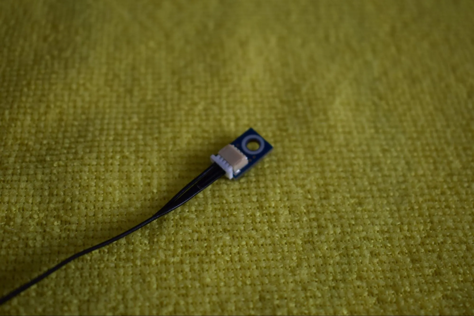
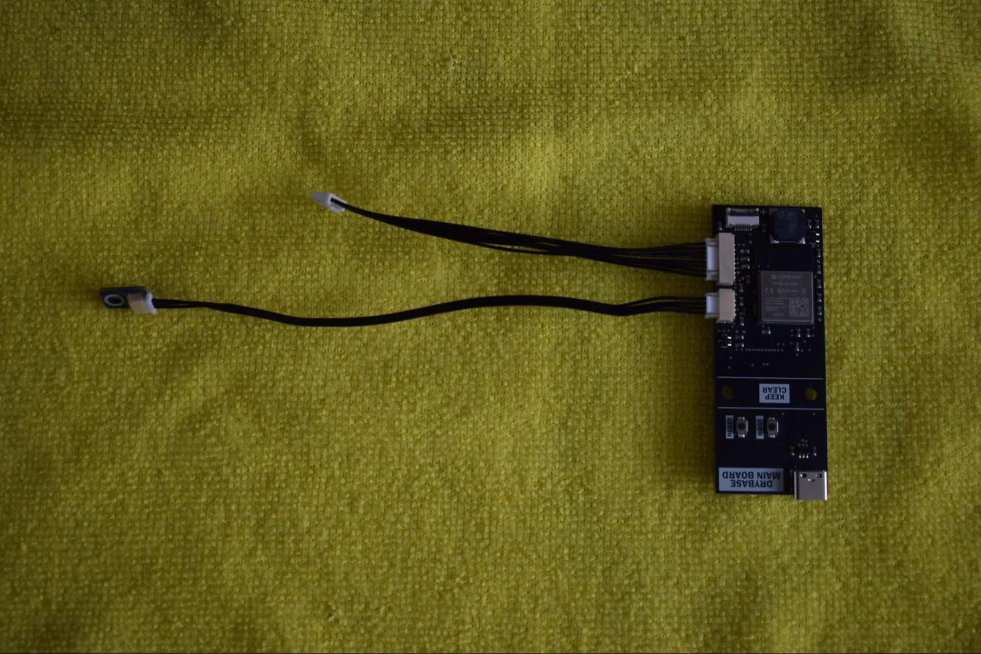
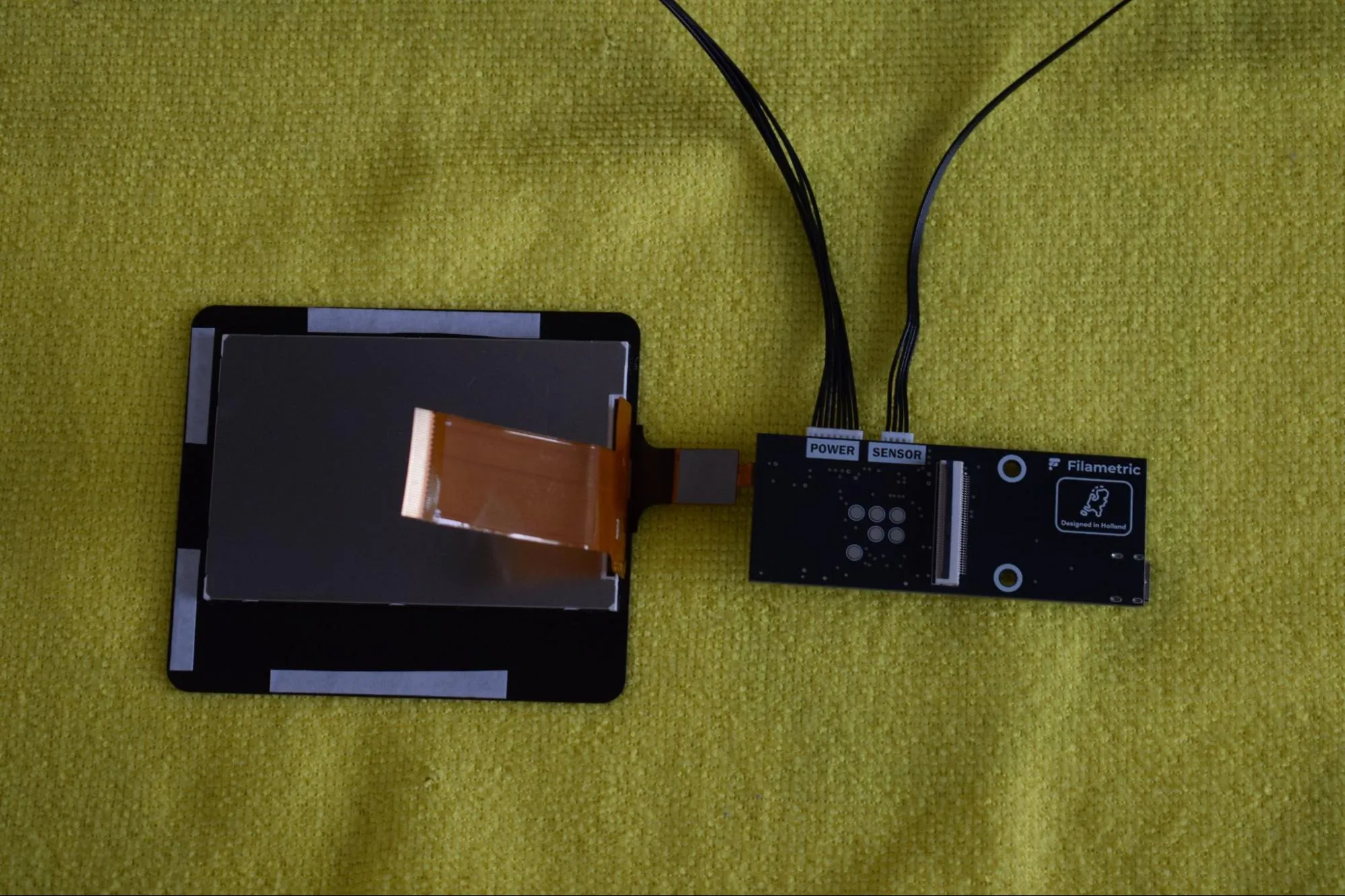
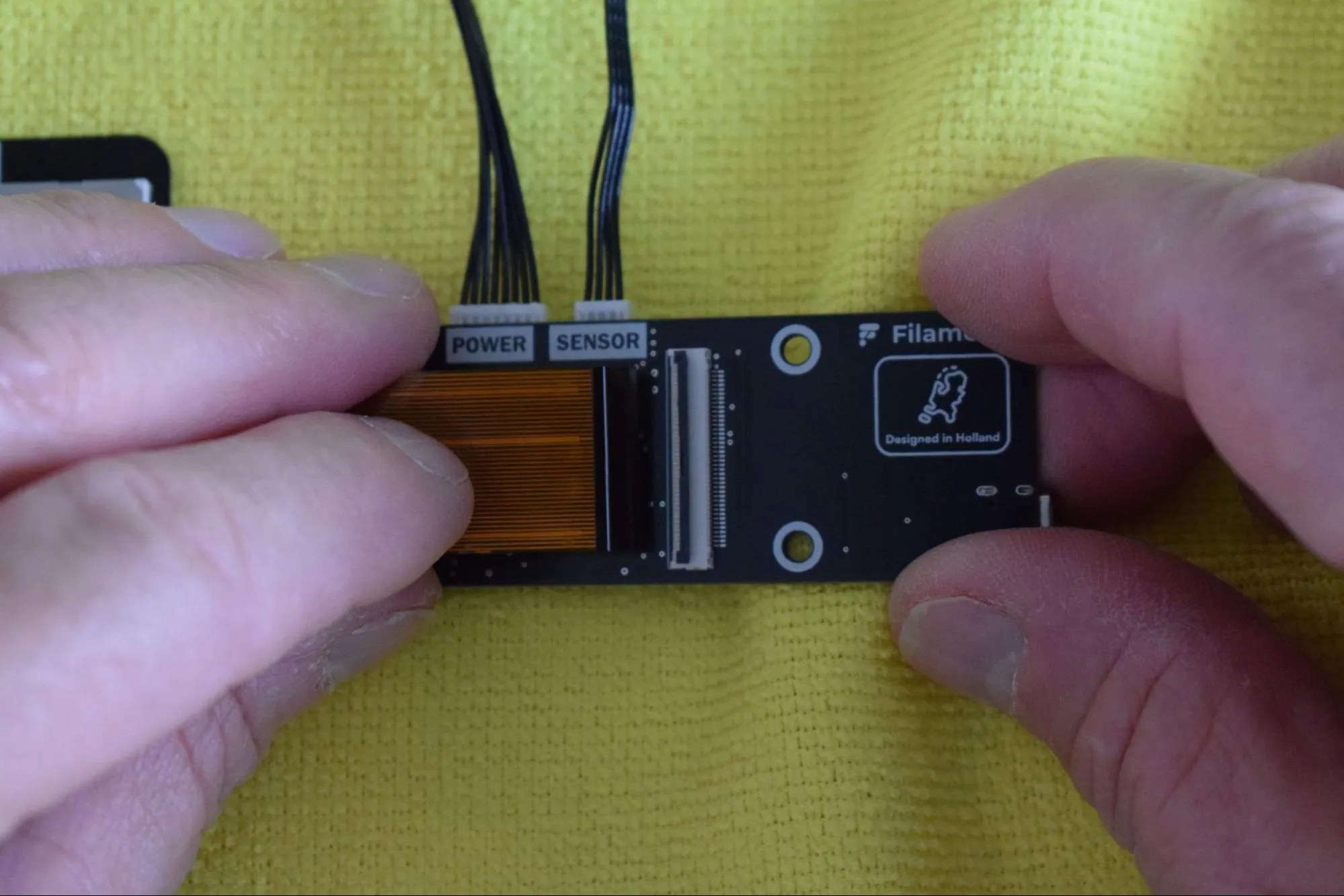
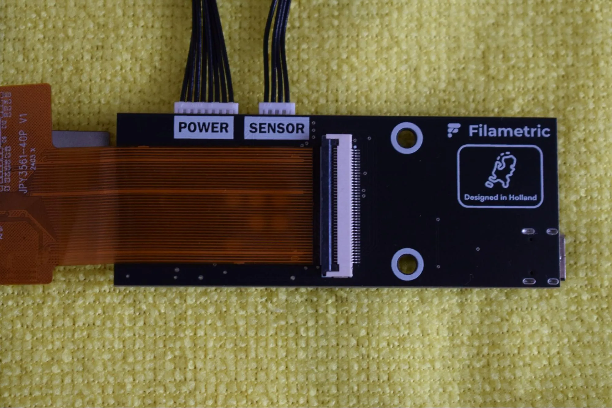
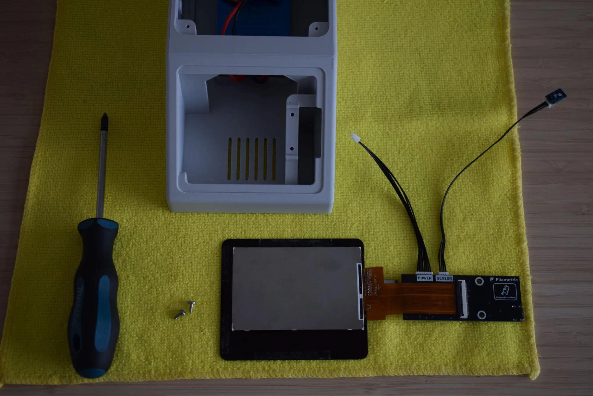
a. Remove both cables and the Main & Sensor board from their bags. Place them on the microfiber cloth as shown in the image below.
b. Connect both cables to the Main board. A clear click should be heard when each connector is fully seated. Give each cable a gentle tug to confirm it is secure.
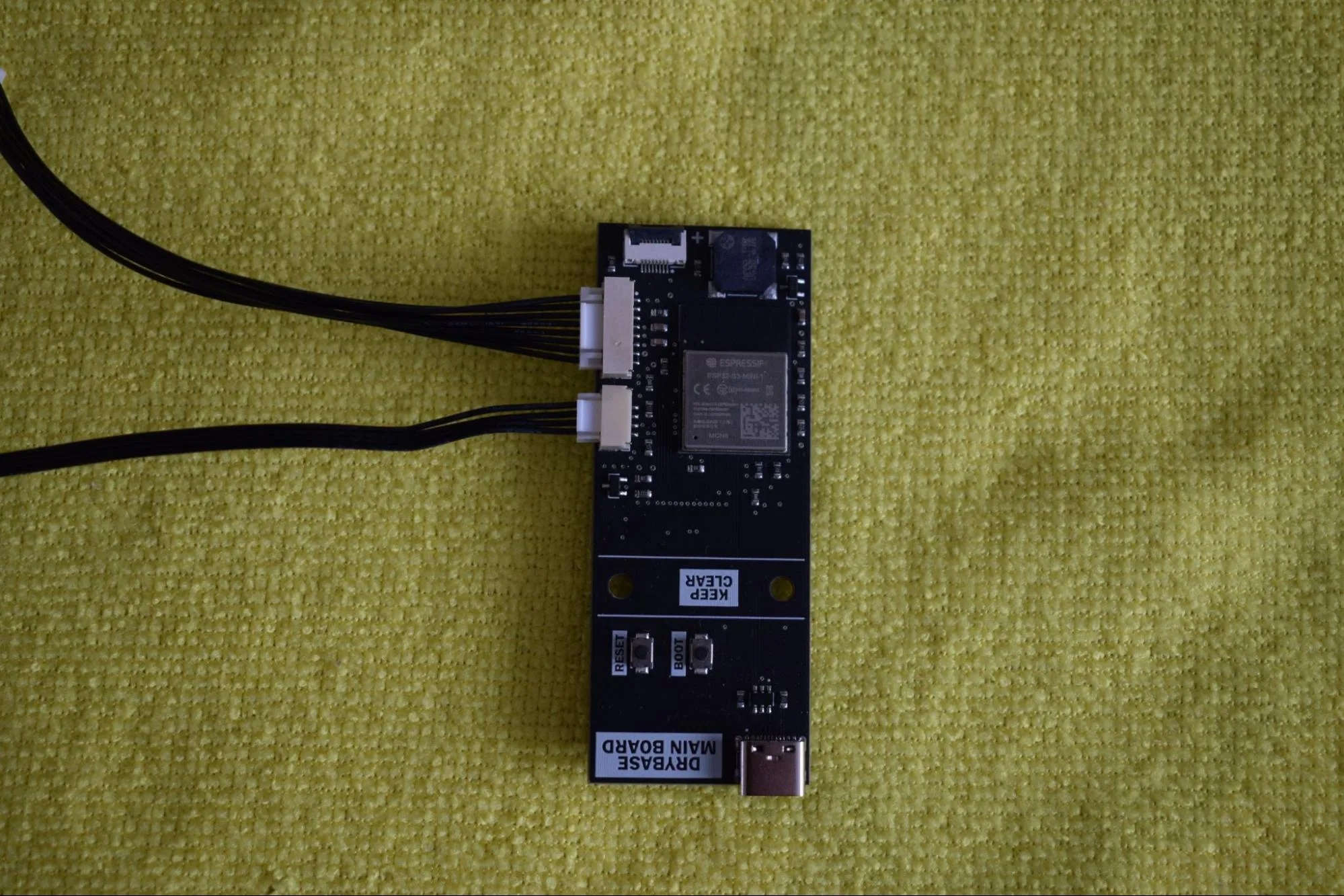
c. Connect the Sensor board to the other end of the 4-wire cable. This connector slides in without a click (it is seated correctly when it sits flush as shown in the image below).
Confirm that the assembly matches the image below before continuing.
d. Remove the display from its bag.
Handle with care
Only touch the FPC cables at their middle and never at the exposed pads or connectors. Oil and pressure from your fingers can damage the contacts.
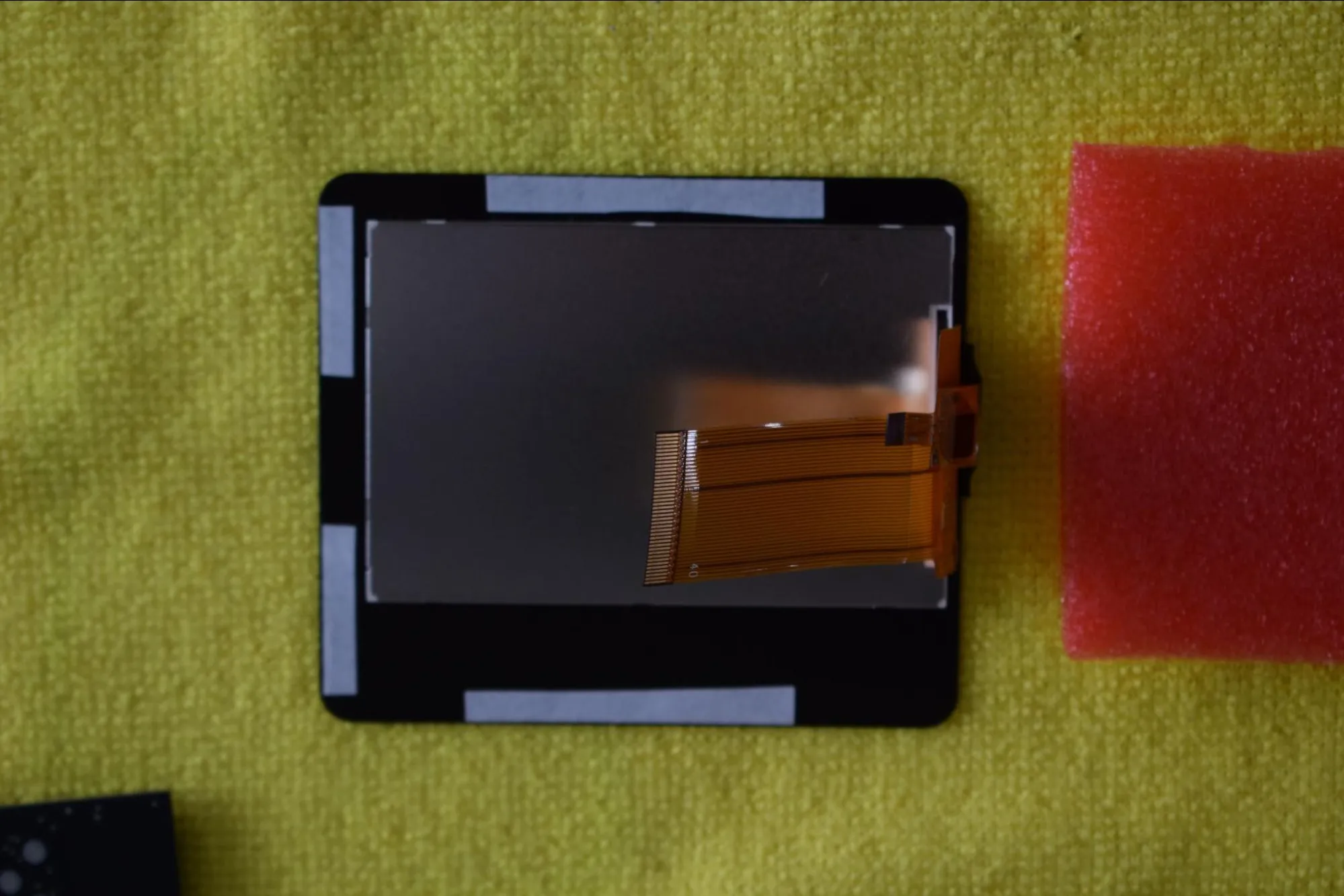
e. Remove the red foam protection from the display and place the display face-down on the microfiber cloth, as shown in the image below.
f. On the Main board, locate both FPC connectors and open them by gently lifting the locking tab, as shown in the images below. Do this carefully, as the tabs are fragile.
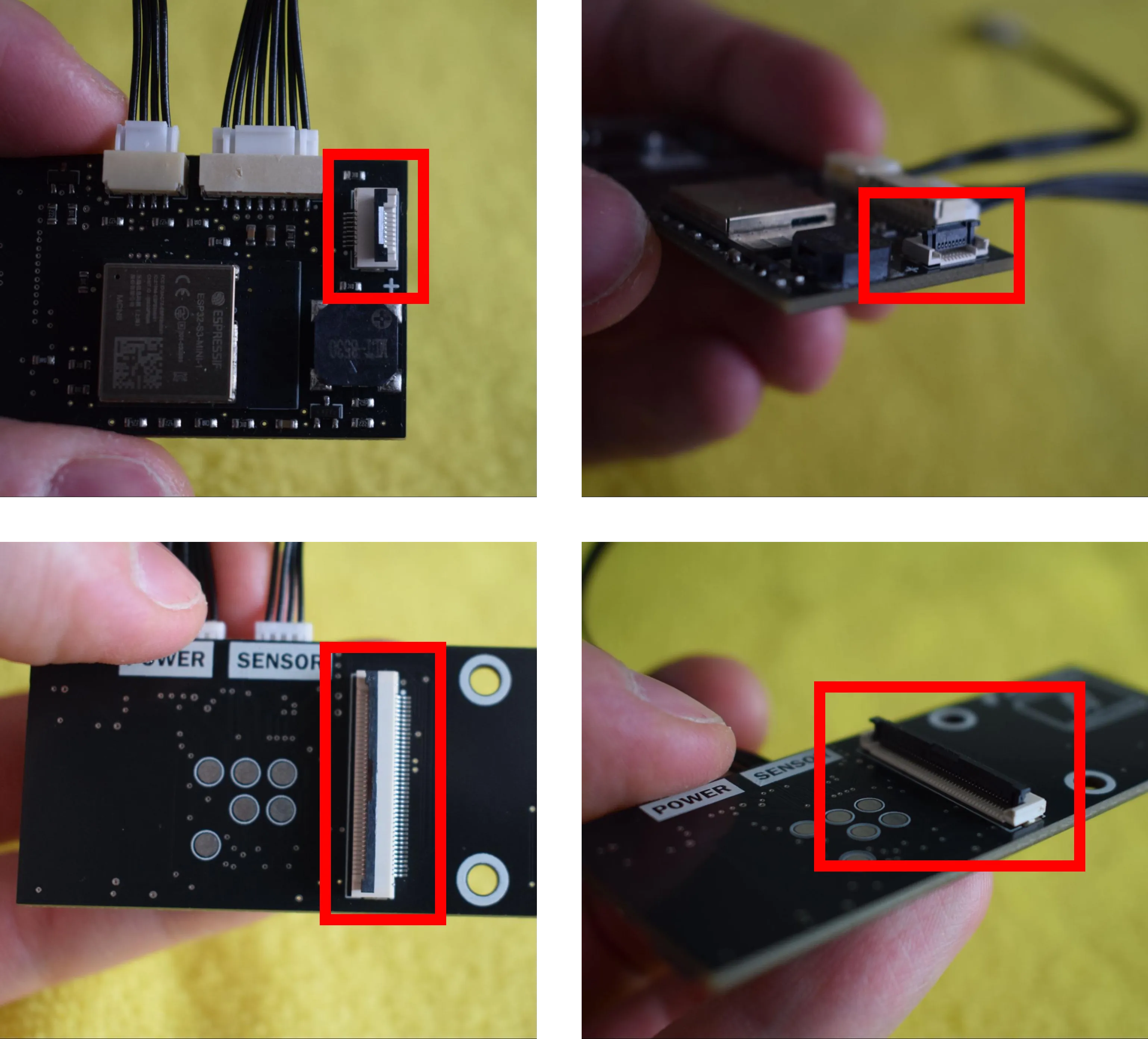
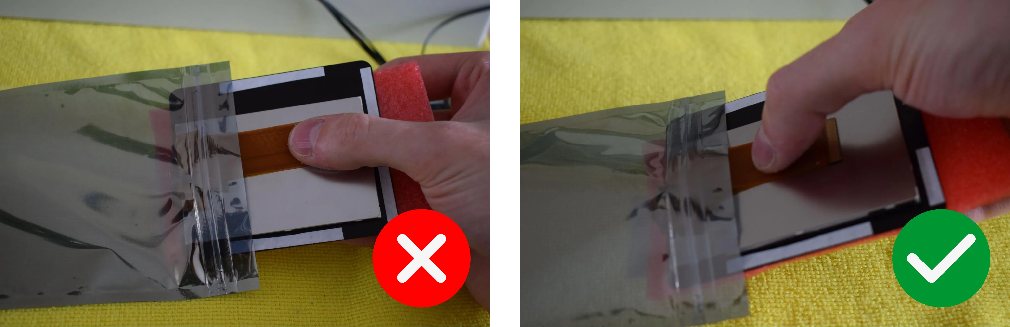
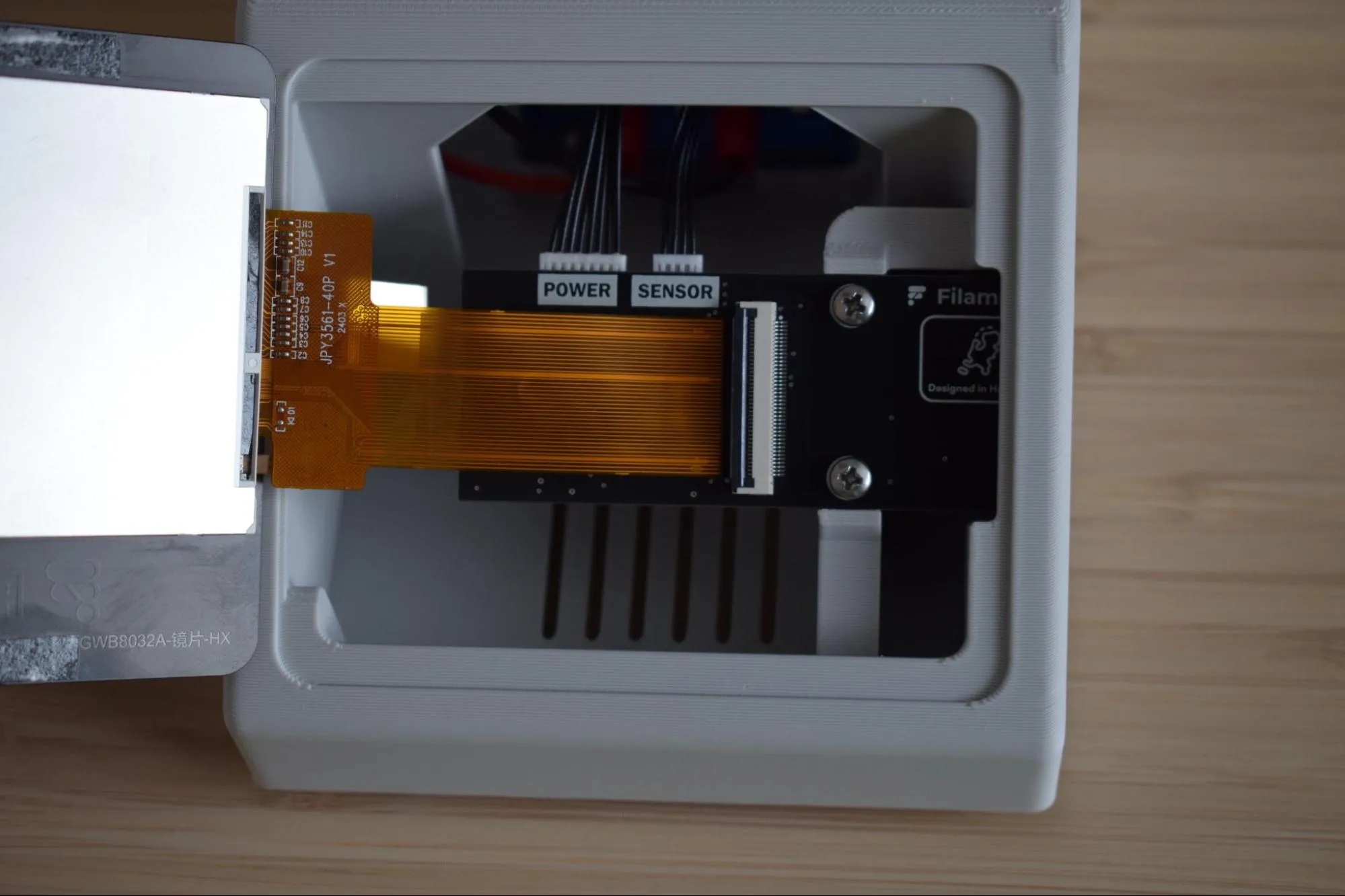
g. Hold the Main board in your left hand and the small FPC touch cable in your right. Refer to the image below to identify the correct cable and connector.
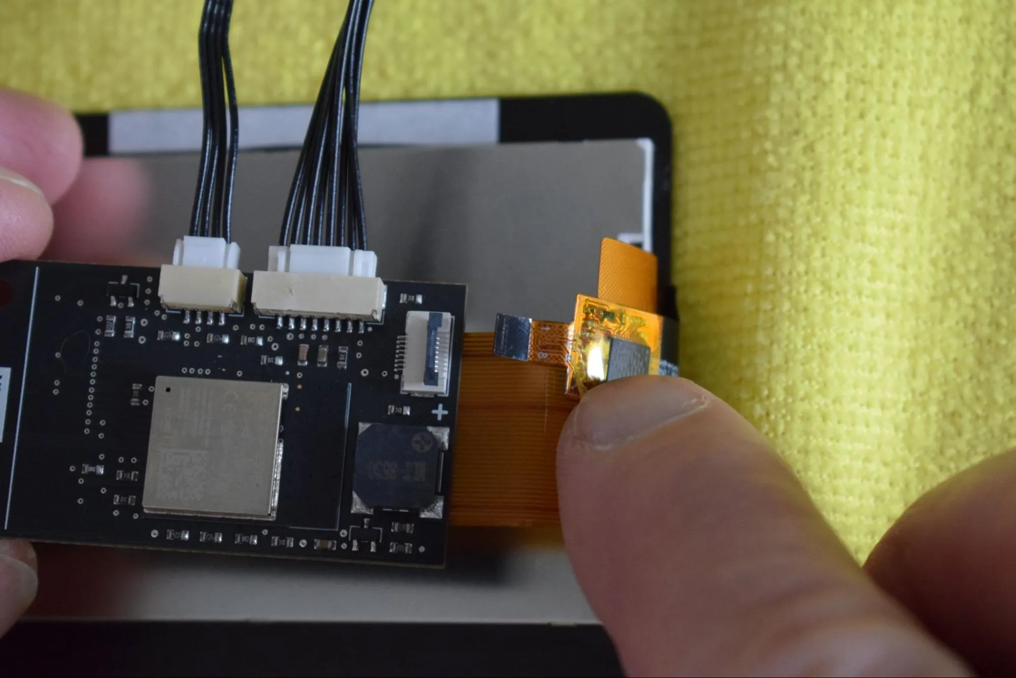
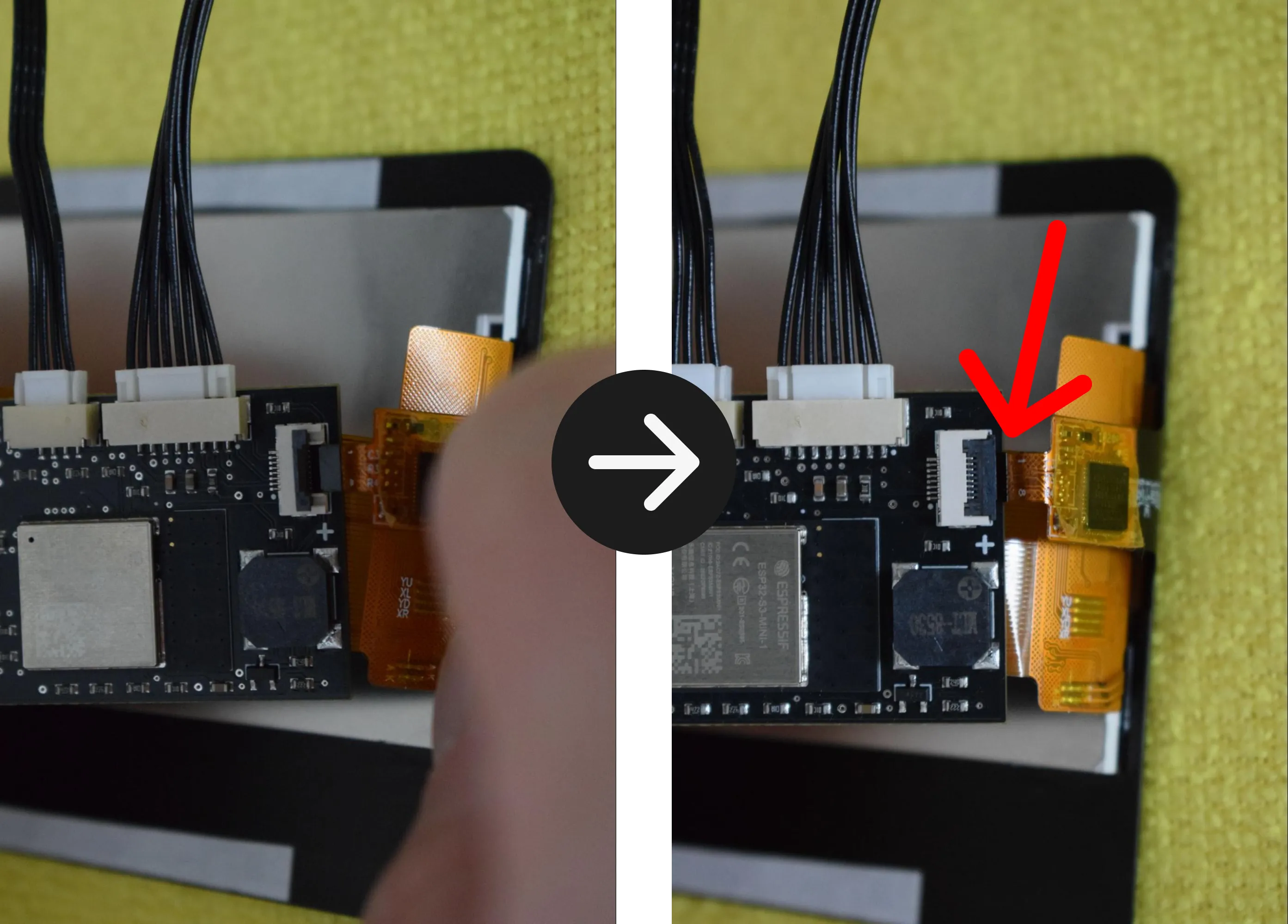
h. Gently slide the cable into the connector until it is fully seated. The black edge of the FPC touch cable should extend ever so slightly beyond the connector, as indicated by the red arrow in the image on the right below. Once correctly positioned, close the locking tab by pressing it down gently until it clicks into place. Do not force it.
i. Flip the Main board over so the FPC display connector is now facing up, and position it alongside the display as shown in the image below.
j. Hold the large FPC display cable in your left hand and the Main board in your right, as shown in the image below.
k. Slide the cable into the wide FPC connector, aligning the white line on the cable with the white line marking on the Main board. Once correctly positioned, close the locking tab by pressing it down gently to secure the connection.
Step 9: Installing the display assembly into the housing
You will need:
- Housing assembly (from a previous step)
- Display assembly (from the previous step)
- 2x 2.9 x 6.5mm round-headed screws (DIN7981; from the Screws / Fasteners bag)
- Microfiber cloth
- Phillips screwdriver
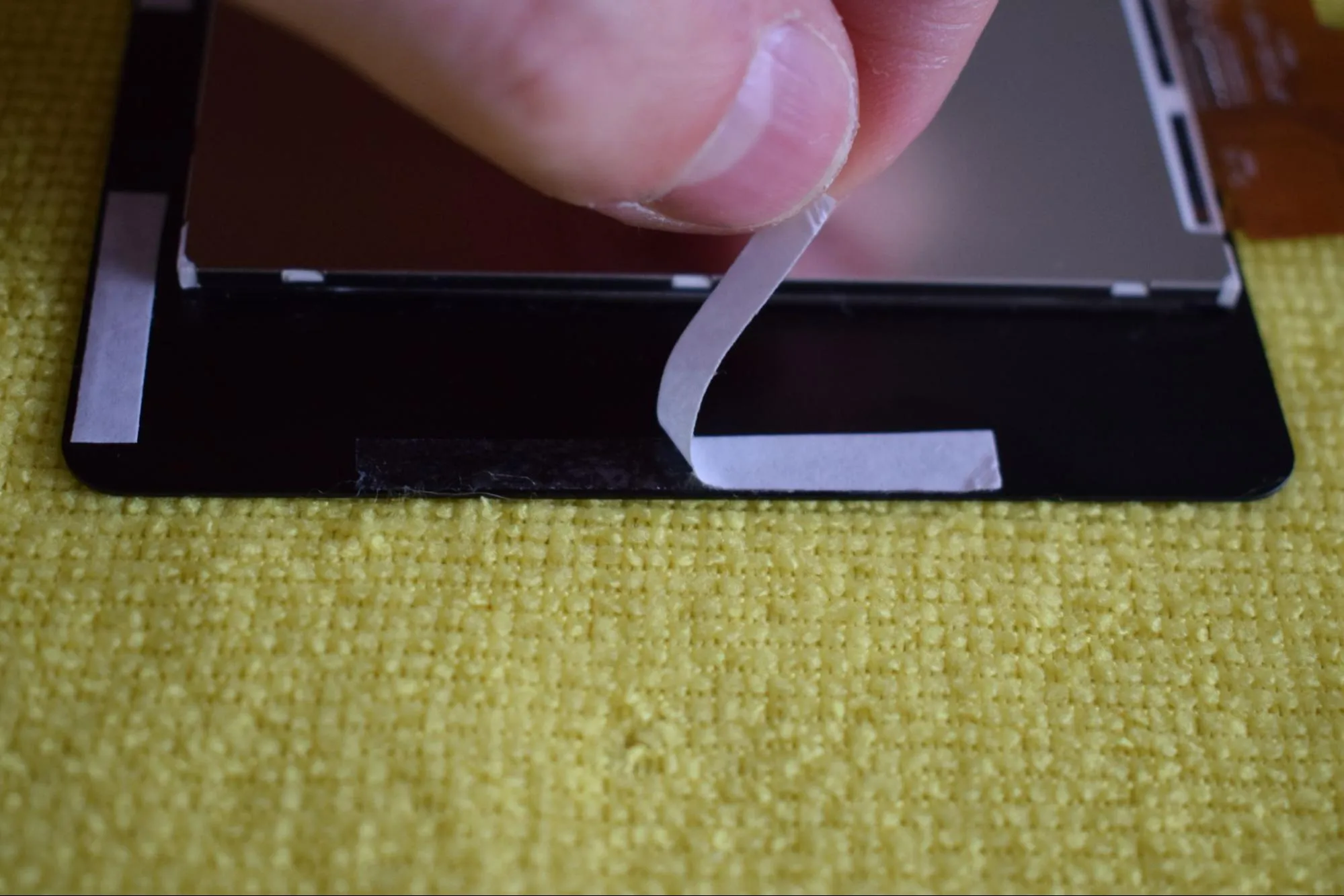
a. Remove the protective film from the self-adhesive tape on the back of the display, as shown in the image below.
b. Hold the display in your left hand and the Main board in your right. Pass both cables through the front opening of the housing, as shown in the image below.
Keep the display cables straight
The FPC cables connecting the display to the Main board are fragile. Keep them as straight as possible at all times to avoid damage to the cables or the FPC connectors on the boards. Do not bend, fold or crease them.
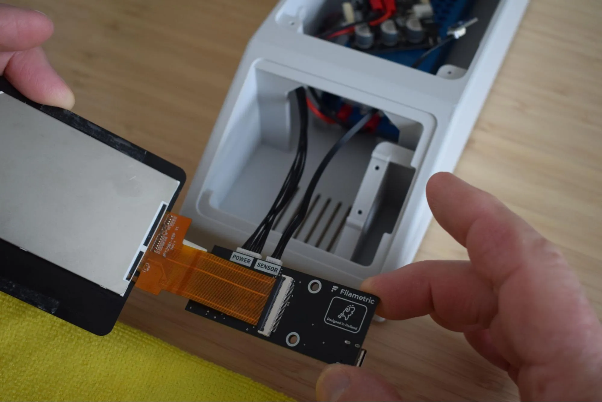
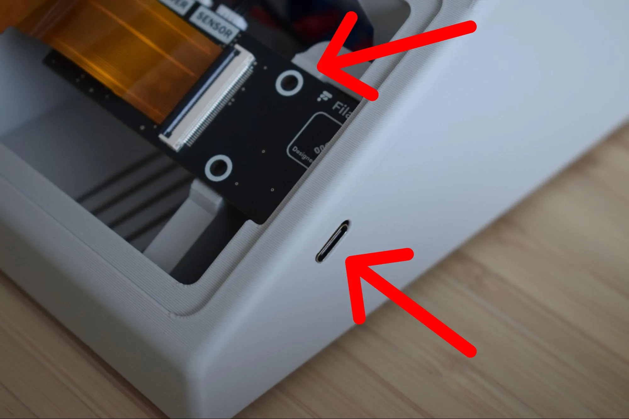
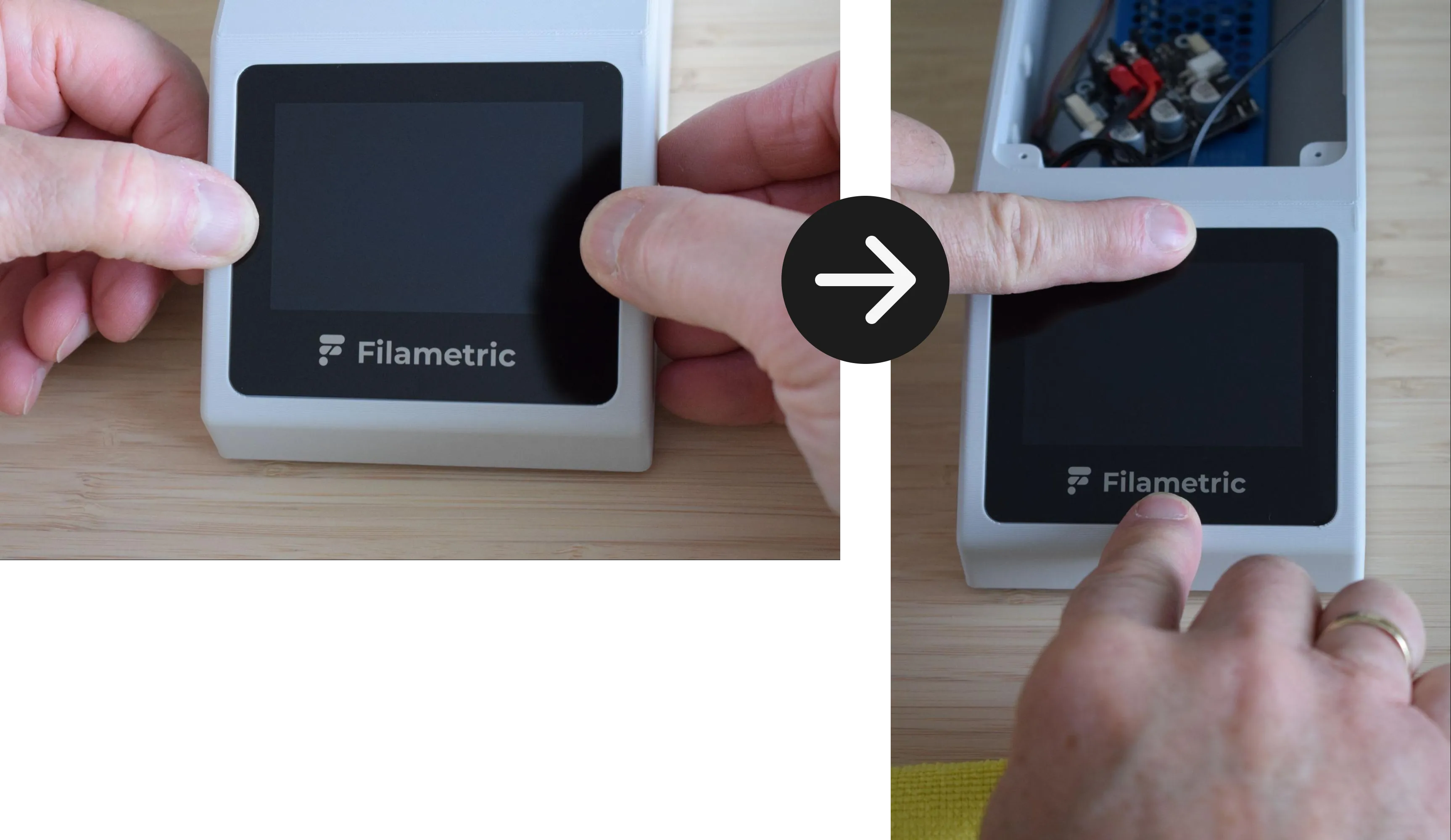
c. While still holding the display with your left hand, insert the Main board into the housing at an angle. Align the top edge of the board flush with the top edge of the housing, as indicated by the top red arrow in the image below. At the same time, align the USB-C connector of the board with its dedicated slot in the housing, as indicated by the bottom red arrow.
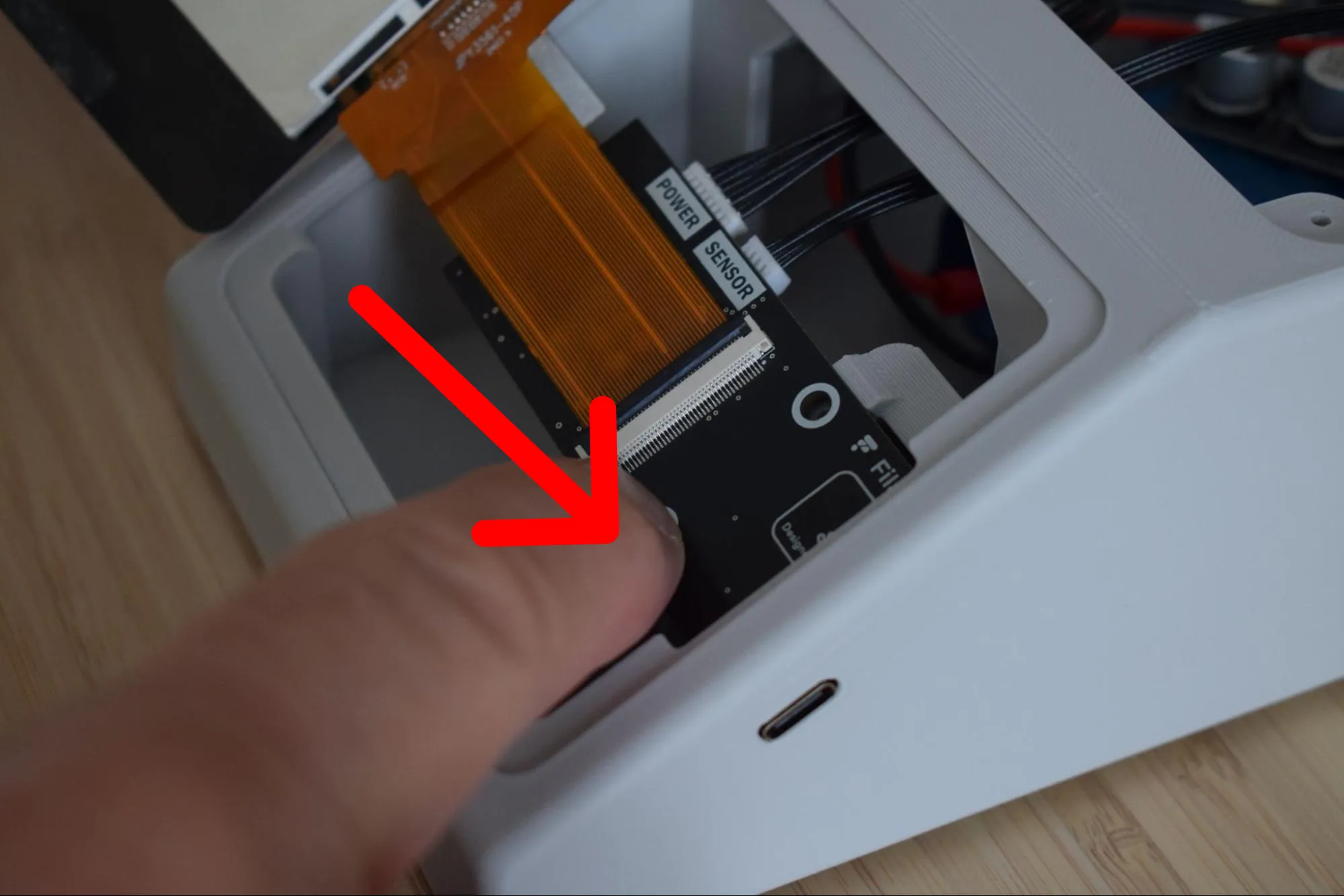
d. Once everything is correctly aligned, apply light pressure with your finger on the bottom of the board as indicated by the arrow in the image below, until it snaps into place. A clear click should be heard when it is fully seated.
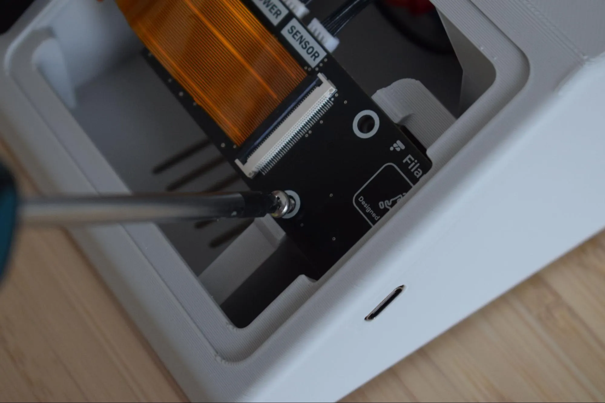
e. Confirm that the Main board is flush with the housing and that the USB-C port is correctly seated in its slot. Then, using your Phillips screwdriver, secure the Main board with both 2.9 x 6.5mm round-headed screws as shown in the image below. Continue holding the display in place with your left hand while tightening.
Do not overtighten
The housing is 3D-printed and the material can crack or strip if too much force is applied. Stop as soon as the Main board sits firmly in place.
The image below shows how the assembly should look after both screws are tightened.
f. Flip the display over so it faces up, aligning its left edge flush with the left side of the housing, as shown in the image below.
g. Gently press along all four sides of the display (left, right, top, and bottom) to firmly bond the double-sided tape to the housing, as shown in the images below.
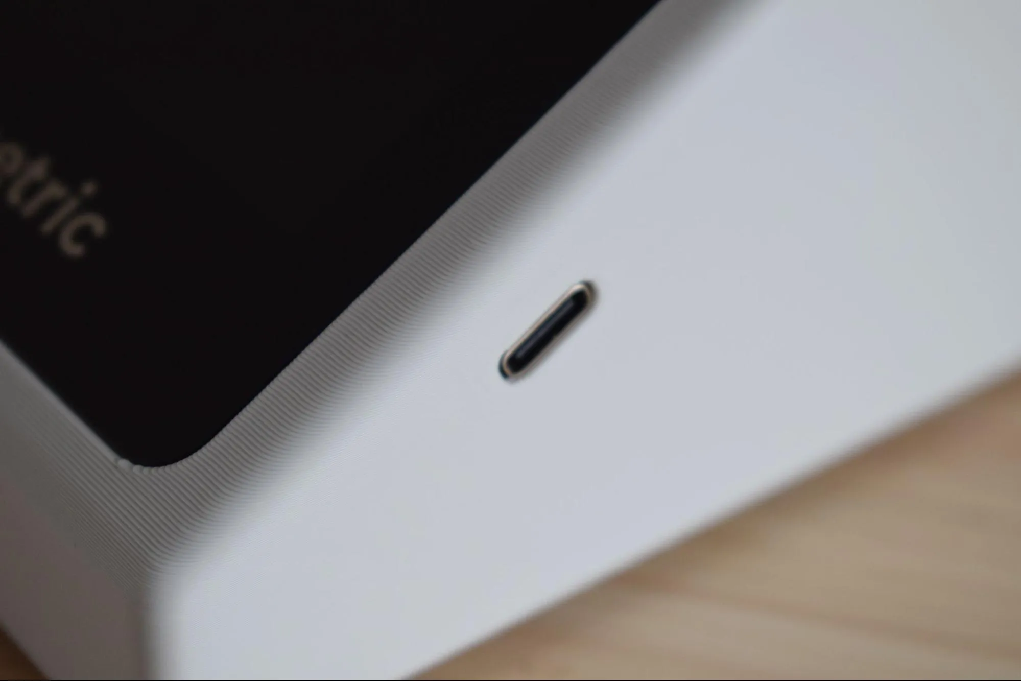
h. Confirm that the display sits flush with the housing on all sides and that the USB-C port is correctly accessible through the housing slot, as shown in the images below.
Step 10: Connecting and securing the Power board
You will need:
- Housing assembly (from a previous step)
- 2x 2.9 x 6.5mm round-headed screws (DIN7981; from the Screws / Fasteners bag)
- Phillips screwdriver
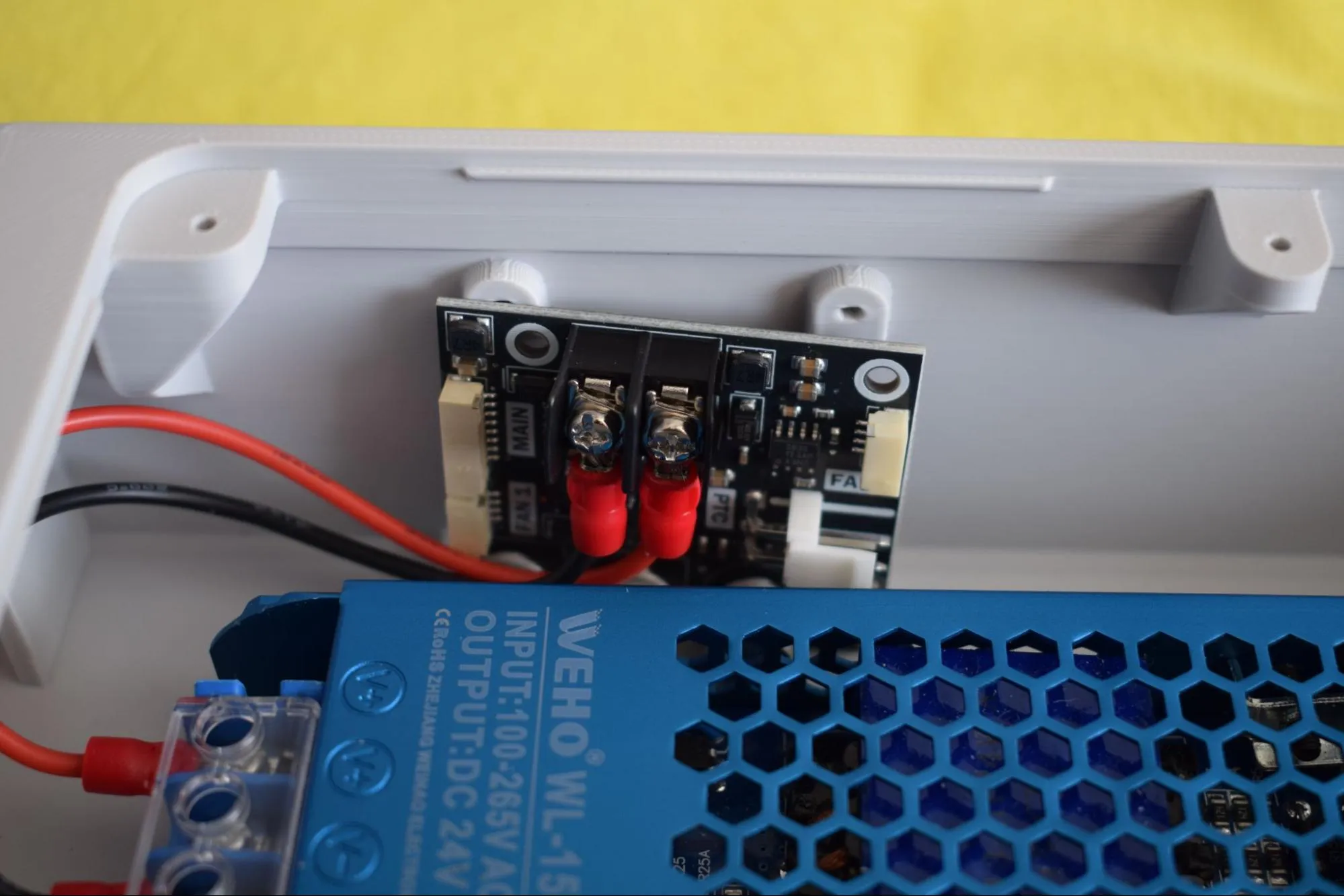
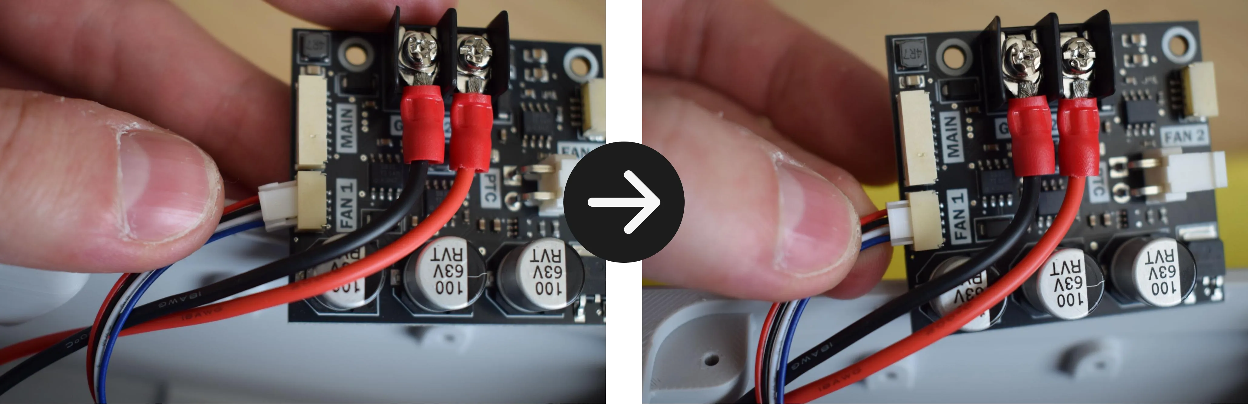
a. Locate the 8-pin cable coming from the Main board and insert it into the connector labeled 'MAIN' on the Power board. A clear click should be heard when fully seated. Give the cable a gentle tug to confirm it is secure.
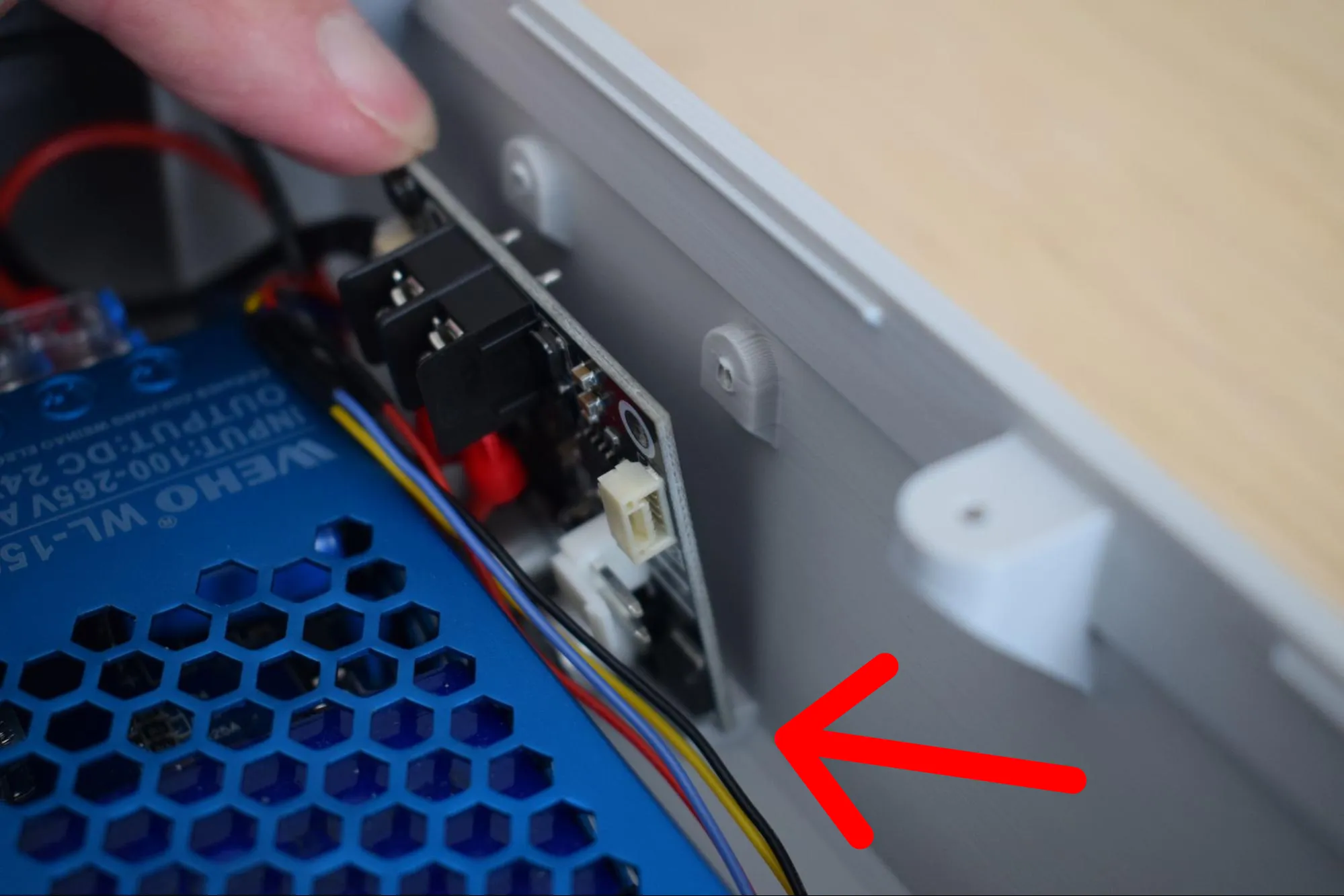
b. Insert the Power board into the dedicated slot in the housing at a slight angle, as indicated by the red arrow in the image below.
Check your cables
Before pressing it into place, make sure no cables are running behind the board. Trapped cables can cause connection issues or damage components.
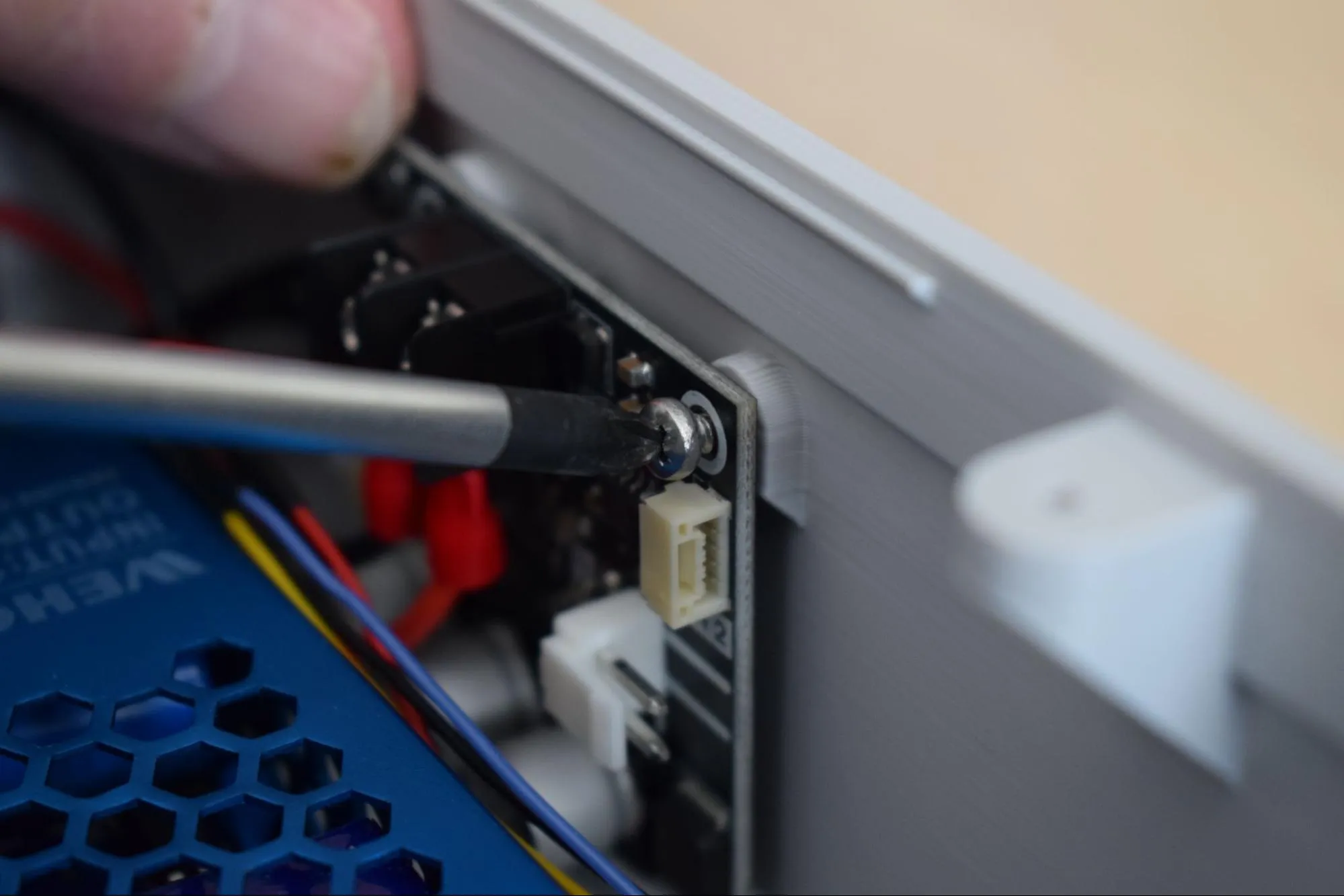
c. Once the board is correctly seated, align both mounting holes and secure the Power board using the two 2.9 x 6.5mm round-headed screws. Angling the screwdriver slightly may help reach the holes more easily.
Do not overtighten
The housing is 3D-printed and the material can crack or strip if too much force is applied. Stop as soon as the Power board sits firmly in place.
d. Confirm that the cables are routed as shown in the images below before continuing.
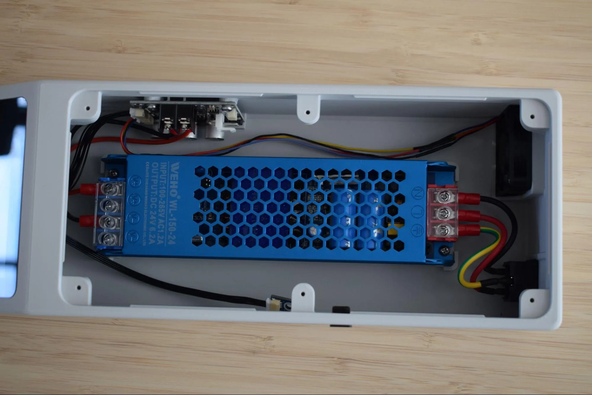
Congratulations! You have completed the housing assembly. The DryBase housing is now fully assembled with all electronics installed and connected. Before continuing to the next chapter, take a moment to verify the following:
- All cables are routed along the inside walls and none are pinched or trapped
- The display sits flush with the housing on all sides
- The USB-C port is accessible through its slot
- The main and power board are each secured with two screws
- The rubber feet are firmly seated in all four corners
In the next chapter, you will assemble the heating unit.
Chapter 4: Heating unit assembly